Cellular communications drive test system and method

a technology of cellular communications and test system, which is applied in the direction of transmission, transmission monitoring, electrical equipment, etc., can solve the problems of system performance waste, inefficient exercise, and inability to accurately ascertain the actual location of the mobile telephone at any given time from the foregoing data s

Inactive Publication Date: 2006-04-13
XYLON LLC +1
View PDF5 Cites 22 Cited by
  • Summary
  • Abstract
  • Description
  • Claims
  • Application Information

AI Technical Summary

Benefits of technology

[0012] To overcome the deficiencies in the conventional methods described above, the present invention provides a system and method whereby the RF engineer need not himself conduct a drive test. Instead, someone else can perform the drive test while the RF engineer remotely accesses the Mobile Telephone Switching Office (MTSO) or Mobile Switching Center (MSC) (“the switch”), places the switch in a call monitor mode and captures telephone call information from both the switch and the mobile telephone (when the cellular system is a digital system) without ever having to leave his office. In addition, the location of the mobile telephone is tracked using data obtained from the Global Positioning System (GPS).
[0022] It is another object of the present invention to remotely access a cellular switch and cause it to record and send call performance information for a particular mobile telephone call.

Problems solved by technology

While the drive test is an effective method for confirming and testing system performance, it is also an extremely inefficient exercise, in terms of time, for an RF
Thus, the drive testing conventionally employed to monitor and upgrade a cellular system's performance wastes an RF engineer's valuable time.
Moreover, even if the data collected by the RF engineer and the switch data are combined in a useful manner for analysis, it is very difficult to ascertain from the foregoing data set the actual location of the mobile telephone at any given time.
However, having only data collected from the mobile telephone and data from the switch cannot provide accurate position location information.
Additionally, the data that is collected from the mobile telephone and switch is often rather “cryptic.” Specifically, while individual parameters such as signal strength, BER, etc. are recorded over time by the switch (and where possible, by the mobile telephone itself), these parameters are output from the switch (and / or mobile telephone) as numeric or text data, which is difficult to understand unless one has extensive knowledge of the various codes and formats employed. FIG. 1 shows a typical “feed” of data from a switch.
This intelligibility difficulty is compounded by the fact that cellular system providers often deploy switches from different manufactures, e.g., Hughes, Lucent or Ericsson, and each of these manufacturers provides call information data in different formats and in different orders.
This makes it particularly difficult to fully appreciate the data that is available, let alone to properly correlate the call information data from the switch with the mobile telephone data, if any, for analysis.

Method used


Image

  • Cellular communications drive test system and method
  • Cellular communications drive test system and method
  • Cellular communications drive test system and method

Examples


Embodiment Construction

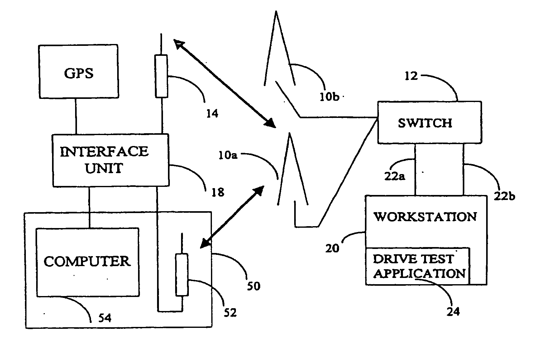
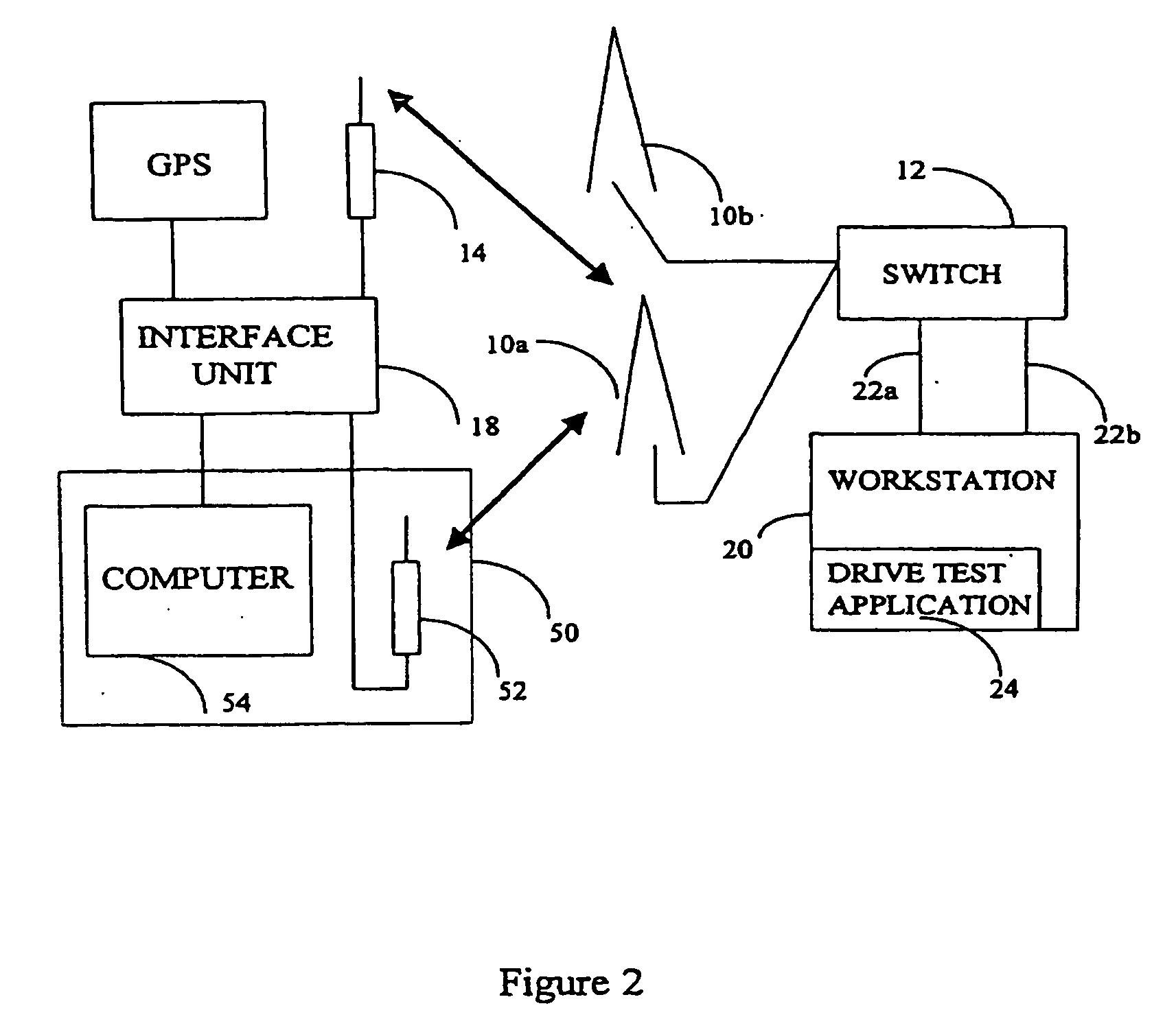
[0034]FIG. 2 schematically illustrates the preferred embodiment of the present invention in which a plurality of cell sites 10a, 10b are in communication with a Mobile Telecommunications Switching Office (MTSO) 12, also sometimes referred to by those skilled in the art as a Mobile Switching Center (MSC), but generally referred to herein as a “switch”. Cell sites 10a, 10b monitor signals transmitted by mobile telephone 14 and pass relevant information to the switch, all in conventional manner. This information typically includes signal strength parameters, and bit error rate (BER) information. Based on this received information, the switch assigns a particular cell site, e.g., 10a, to be the present or next (after a handoff) serving cell for a call initiated or to be received by mobile telephone 14.

[0035] Also shown in FIG. 2 is a workstation 20, such as a personal computer (PC), on which a program for executing the present invention preferably resides. The program, identified as dr...


PUM


Abstract

A system for and method of cellular telephone system monitoring includes a cellular switch which is remotely accessed and placed in a call monitor mode. A GPS receiver is connected to a mobile telephone via an interface unit. Call performance information (e.g., signal strength, BER and call events) are recorded at the switch and downloaded to a remote computer that includes a display. GPS location information is transmitted by the mobile telephone and received by the remote computer via the switch. The computer receives and stores the recorded call and GPS information and graphically displays this information, along with a map indicating the location of the mobile telephone. Preferably, the call information is first parsed, converted and / or scaled to conform to a standard file format.

Description

[0001] This application is a continuation-in-part application of U.S. application Ser. No. 09 / 604,755, filed Jun. 28, 2000, which is incorporated by reference herein.BACKGROUND [0002] 1. Field of the Invention [0003] The present invention is directed to management, testing and maintenance of cellular telephone systems. More particularly, the present invention is directed to a system and method for (i) remotely monitoring the call parameters of a mobile cellular telephone call and (ii) displaying those parameters in a dynamic graphical form in real or near real time, wherein the graphical form also includes the mobile cellular telephone's location. [0004] 2. Background of the Invention [0005] Unfettered mobile telephone network access, call continuity and call clarity are some of the technical considerations that are continually optimized to achieve a high level of mobile cellular telephone service. To achieve improved performance levels, cellular telephone service providers must pos...

Claims


Application Information

Patent Timeline
Patent Type & Authority Applications(United States)
IPC IPC(8): H04Q7/20H04W24/00
CPCH04W24/00H04W24/08
Inventor MARTIN, DANNIE E.
Owner XYLON LLC
Why Eureka
Try Eureka