Marching bass drum supporting structure, marching bass drum, and carrier

a technology for supporting structures and bass drums, which is applied in the direction of instruments, instruments, instruments, etc., can solve the problems of difficult removal of bass drums b>110/b> from carriers,

Inactive Publication Date: 2006-04-20
HOSHINO GAKKI COMPANY LIMITED
View PDF11 Cites 11 Cited by
  • Summary
  • Abstract
  • Description
  • Claims
  • Application Information

AI Technical Summary

Benefits of technology

[0010] One aspect of the present invention is a supporting structure for supporting a marching bass drum with a carrier that is worn by a drummer in a state in which drum heads of the marching bass drum are held in a vertical state. The supporting structure is provided with a first connection mechanism, including a hooking portion arrangable on the carrier and a hooked portion arrangable on the marching bass drum, for movably connecting the marching bass drum to the carrier in a state in which the hooked portion is hooked to the hooking portion. A second connection mechanism connects the marching bass drum to the carrier to restrict movement of the marching bass drum relative to the carrier in a state in which the first connection mechanism movably connects the marching bass drum to the carrier.

Problems solved by technology

However, this structure has a shortcoming in that the removal of the bass drum 110 from the carrier 111 is difficult.

Method used


Image

  • Marching bass drum supporting structure, marching bass drum, and carrier
  • Marching bass drum supporting structure, marching bass drum, and carrier
  • Marching bass drum supporting structure, marching bass drum, and carrier

Examples


first embodiment

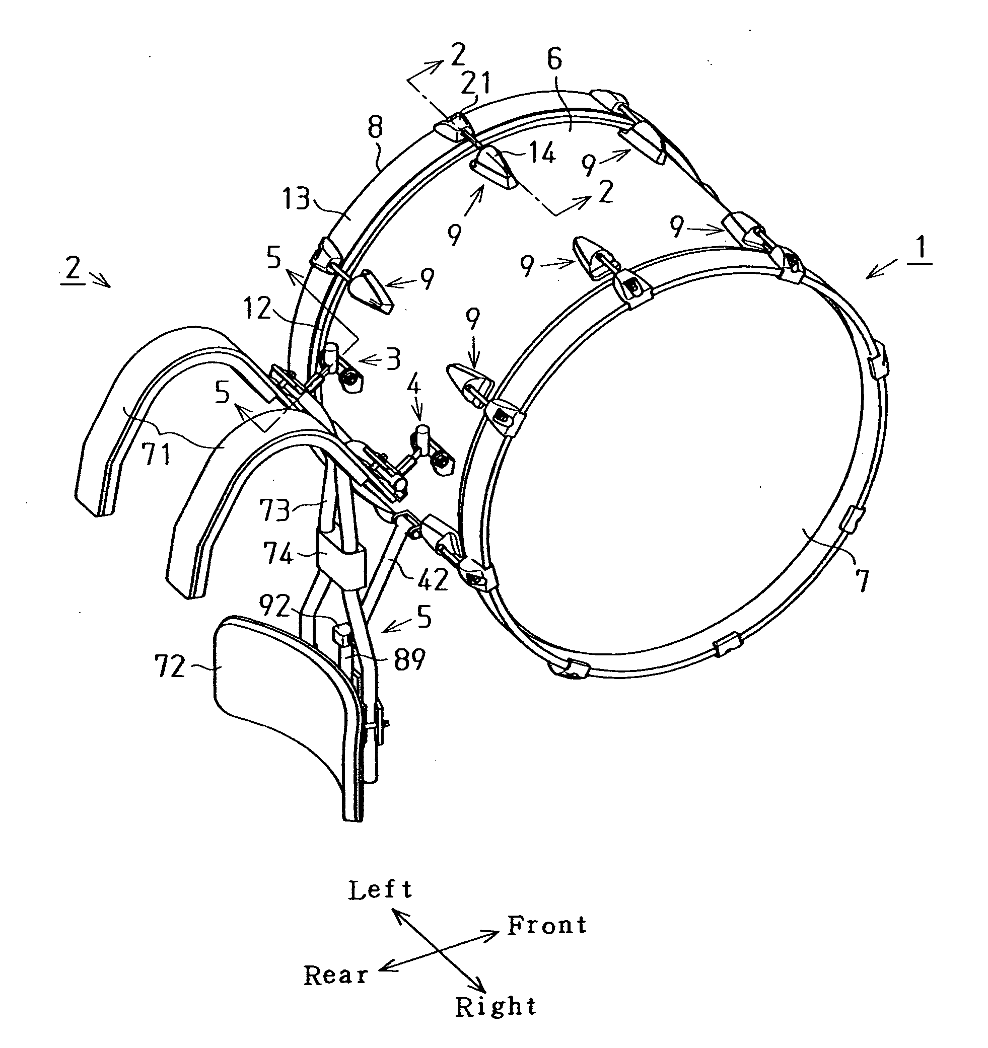
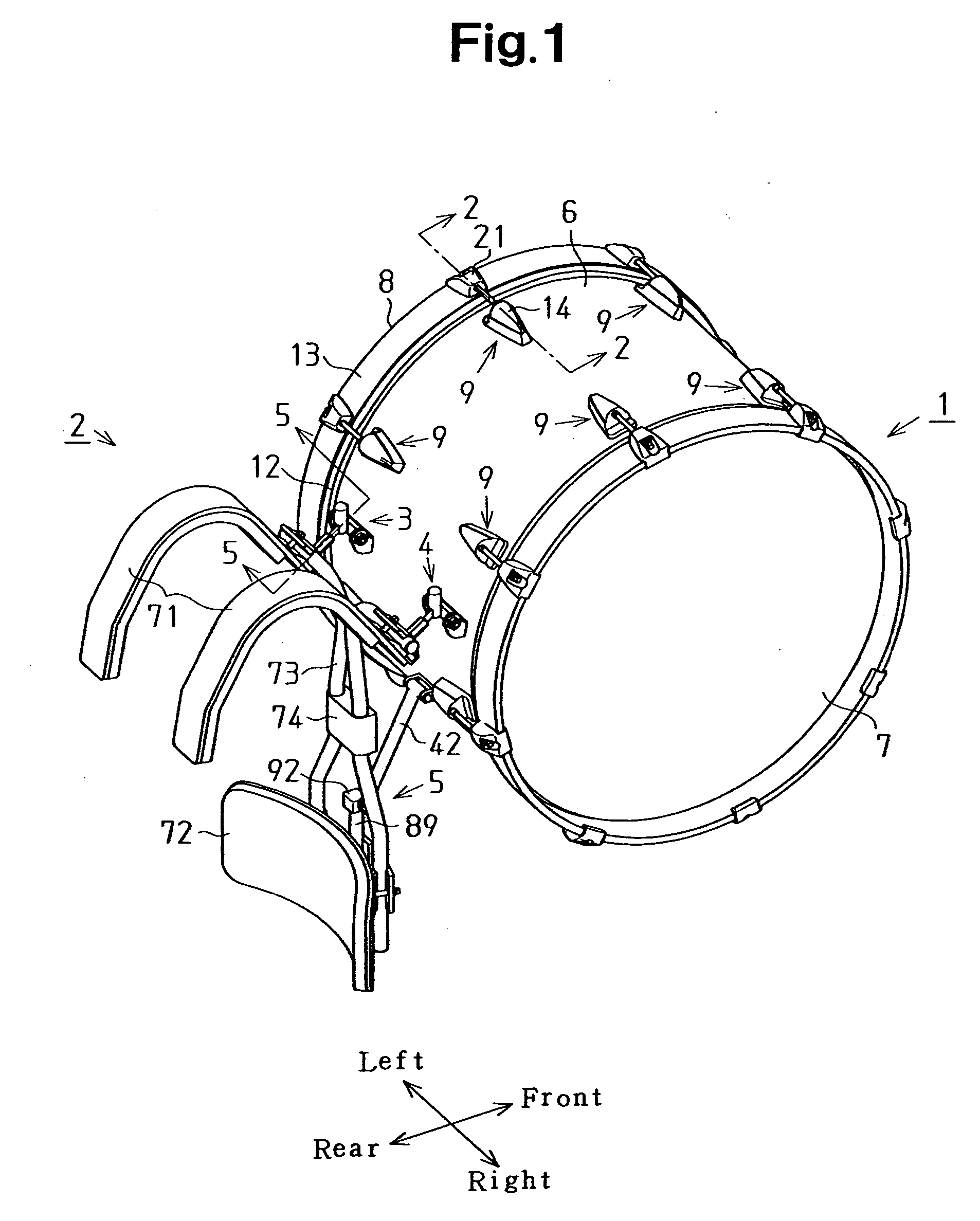
[0030] A first embodiment of the present invention will now be described with reference to FIGS. 1 to 10. FIG. 1 shows a marching bass drum (hereafter simply referred to as a “bass drum”) 1 in a state mounted on a carrier 2. As shown in FIG. 1, the bass drum 1 is mounted on the carrier 2 by upper first connection mechanisms 3 and 4, which are arranged at two locations, and a lower second connection mechanism 5, which is arranged at one location. The side of the drum farthest from the drummer when the drummer is wearing the carrier 2 that holds the bass drum 1 (the bass drum 1 side in FIG. 1) is hereafter referred to as the “front” of the bass drum 1, and the right side of the drummer is hereafter referred to as the “right” side of the bass drum 1. In the present embodiment, as shown in FIG. 10, a plurality of bass drums 1 that differ in size (bass drums 1a, 1b, and 1c) can be selectively mounted on the carrier 2 by the first connection mechanisms 3 and 4 and the second connection me...

second embodiment

[0083] A second embodiment of the present invention will now be described with reference to FIGS. 11 to 13. In the present embodiment, like or same reference numerals are given to those components that are the same as the corresponding components of the first embodiment. The present embodiment will be described focusing on points differing from the first embodiment. The present embodiment is the same as the first embodiment in that a bass drum 1 is mounted on a carrier 2 by connection mechanisms arranged at a total of three locations, that is, first connection mechanisms 3 and 4 arranged at two locations and a second connection mechanism 5 arranged at one location. The structures of the first and second connection mechanisms differ from the corresponding structures in the first embodiment.

[0084]FIG. 11 shows the supporting structure of the marching bass drum 1 according to the present embodiment in a state in which the marching bass drum 1 is mounted on the carrier 2. FIG. 12 shows...


PUM


Abstract

A carrier for holding a bass drum with two first connection mechanisms and one second connection mechanism. The second connection mechanism includes a connection member, which is arranged on the bass drum, and a slide member, which is arranged on the carrier. The distal end of the slide member is engaged with the connection member. Each first connection mechanism includes a hook receptacle, which is arranged on the bass drum and open in a downward direction, and a hook, which is arranged on the carrier and inserted in the receptacle.

Description

BACKGROUND OF THE INVENTION [0001] The present invention relates to a marching bass drum supporting structure, a marching bass drum, and a carrier. [0002] In the prior art, a carrier (holder) used exclusively for a marching bass drum (hereafter simply referred to as a “bass drum”) is known. One example of such a carrier is described in U.S. Pat. No. 6,323,407. The carrier enables the drummer to play the bass drum with its drum heads held in a vertical state. FIG. 14 is a perspective view showing a carrier 111 for a bass drum 110, as described in U.S. Pat. No. 6,323,407. In FIG. 14, the side of the drum farthest from the drummer when the drummer is wearing the carrier 111 is hereafter referred to as the “front” of the drum. [0003] As shown in FIG. 14, the carrier 111 includes two reverse U-shaped straps 112, an abdomen contact plate 113, and an arm 114. The abdomen contact plate 113 comes into contact with the drummer's abdomen. The arm 114 links the straps 112 and the abdomen contac...

Claims


Application Information

Patent Timeline
Patent Type & Authority Applications(United States)
IPC IPC(8): G10D13/02
CPCG10G5/005
Inventor SHIMADA, MASAHIRO
Owner HOSHINO GAKKI COMPANY LIMITED
Why Eureka
Try Eureka