Combined filter and fill tube

a technology of filling tube and filter, which is applied in the direction of machines/engines, mechanical equipment, transportation and packaging, etc., can solve the problems of large size of the breather assembly, large size of the breather system that uses filters, and occupying excessive engine compartment spa

Active Publication Date: 2006-04-20
INT ENGINE INTPROP CO LLC
View PDF14 Cites 40 Cited by
  • Summary
  • Abstract
  • Description
  • Claims
  • Application Information

AI Technical Summary

Problems solved by technology

A small amount of these gases leaks past the piston seals of the internal combustion engine, and unless the gases are removed from the crankcase, they become trapped.
Existing breather systems are si

Method used


Image

  • Combined filter and fill tube
  • Combined filter and fill tube
  • Combined filter and fill tube

Examples


Embodiment Construction

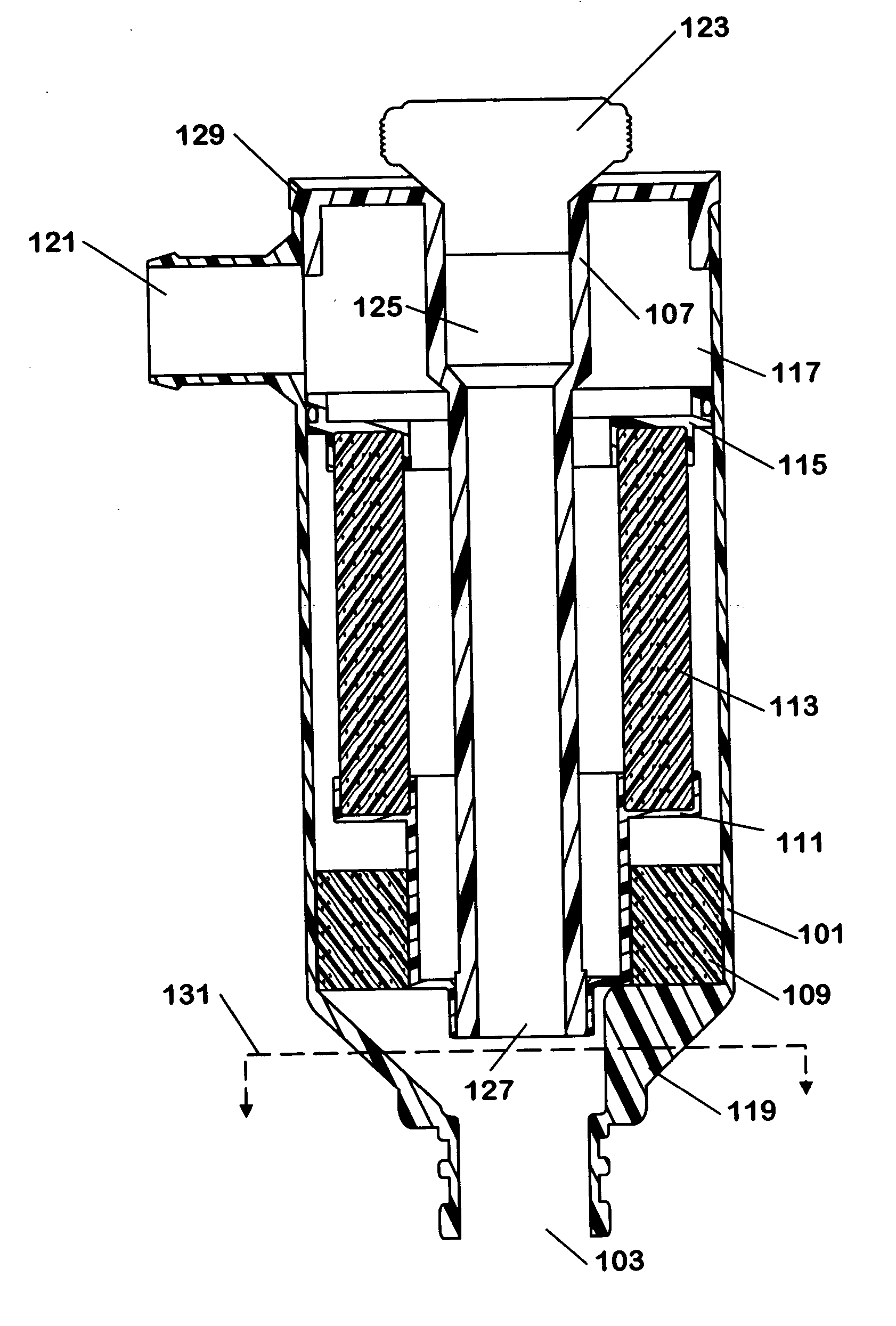
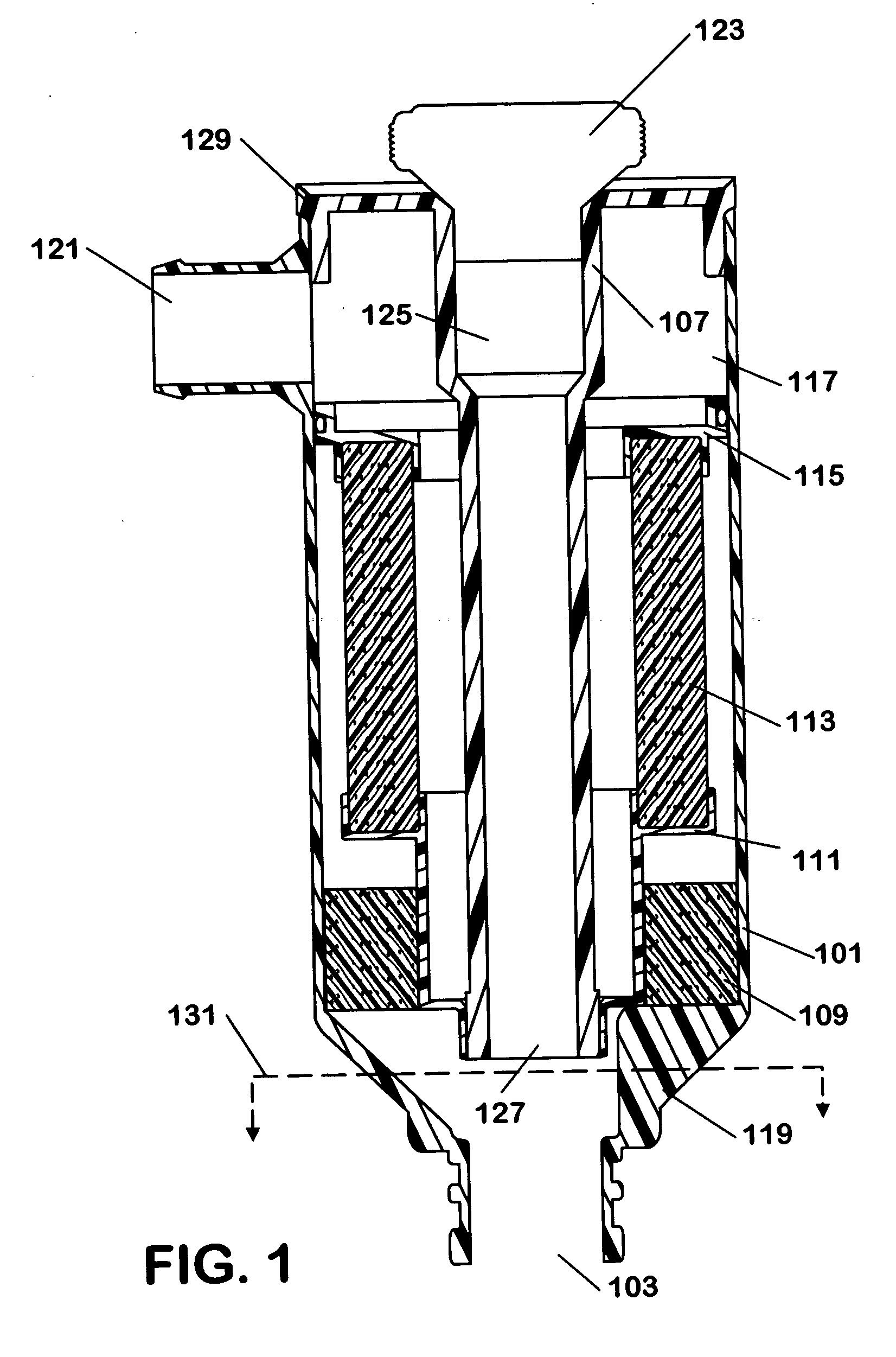
[0012] The following describes an apparatus for and method of filtering oil mist from a gas stream while providing a passage for adding oil through the same apparatus to an internal combustion engine. The apparatus is compact and efficient at separating oil mist from blow-by gases.

[0013] A cross-sectional view of an integrated oil separator and oil fill tube is shown in FIG. 1. A housing 101 has a passage 103 at one end. A plurality of ribs 119 (see FIG. 3) are disposed above the passage 103. The passage 103 is in fluid communication with, for example, an internal combustion engine. An oil fill tube 107 is disposed in the housing 101 and advantageously has a centerline substantially parallel to the centerline of the housing 101. A fluid inlet 125 at one end of the oil fill tube 107 is advantageously shaped like a funnel. At the opposite end of the fill tube 107, a fluid outlet 127 is located near the ribs 119 and above the passage 103. Resting above the ribs 119 is an optional pre-...


PUM

PropertyMeasurementUnit
Pressureaaaaaaaaaa

Abstract

An apparatus includes a housing (101), a fill tube (107) disposed within the housing (101), the fill tube (107) having a fluid inlet (125) at one end and a fluid outlet (127) at another end. The fluid outlet (127) is disposed near a passage (103) of the housing (101) such that fluid entering the fluid inlet (125) exits the housing (101) through the passage (103). A filter (113) is disposed outside the fill tube (107) and inside the housing (101), such that unfiltered gases from the passage (103) are capable of entering the filter (113). A gas outlet (121) is integrated with the housing (101), such that filtered gases from the filter (113) are capable of exiting the housing (101) through the gas outlet (121).

Description

FIELD OF THE INVENTION [0001] This invention relates to internal combustion engines, including but not limited to recirculation of crankcase gases into the intake system of an engine. BACKGROUND OF THE INVENTION [0002] Combustion gases are generated during the operation of an internal combustion engine. A small amount of these gases leaks past the piston seals of the internal combustion engine, and unless the gases are removed from the crankcase, they become trapped. These gases, commonly referred to in the art as blow-by gases, need to be released from the crankcase and are usually recirculated into the engine air intake system. Blow-by gases that are released from the crankcase sometimes carry combustion by-products. Splashing of the engine's rotating components as well as oil circulating within the crankcase and the oil pan generate oil mist in the blow-by gases. It is desirable to remove the oil mist from the gas prior to introduction into the intake air system. An apparatus tha...

Claims


Application Information

Patent Timeline
IPC IPC(8): F02B25/06
CPCB01D46/0024B01D2279/00F01M13/04F01M13/0405F01M2011/0491F01M2013/0438F02M25/06Y02T10/121Y02T10/12B01D46/64
Inventor GRONBERG, PHILIP F.LYONS, TIMOTHY M.
Owner INT ENGINE INTPROP CO LLC
Why Eureka
Try Eureka