Hydraulic or pneumatic machine with tilting blades

Inactive Publication Date: 2006-04-20
HOLT CORNELIU
View PDF5 Cites 14 Cited by
  • Summary
  • Abstract
  • Description
  • Claims
  • Application Information

AI Technical Summary

Benefits of technology

[0011] the possibility of making pneumatic machines, engines or compressors where the prolonged expansion or fluid compression respectively is achieved in circuits consisting of one or several channels coupled in series or in parallel, the small pressure differences between the compartments formed along the channels, between the successive blades of each rotor, resulting in low stresses in the tilting blades and in

Problems solved by technology

Such machines have the disadvantage of a sturdy, sophisticated, low efficiency construction.
There are also hydraulic or pneumatic machines—motors or pumps—using pressure working fluids, being equipped either with gliding blades in the rotor or hinged blades on it, having the

Method used


Image

  • Hydraulic or pneumatic machine with tilting blades
  • Hydraulic or pneumatic machine with tilting blades
  • Hydraulic or pneumatic machine with tilting blades

Examples


example 1

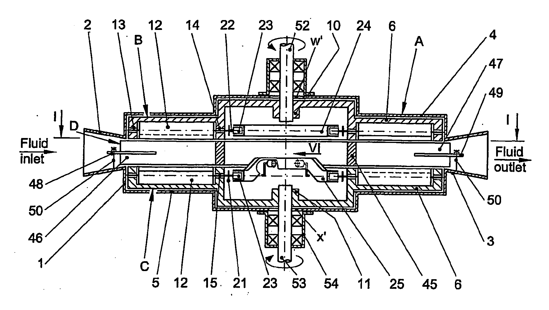
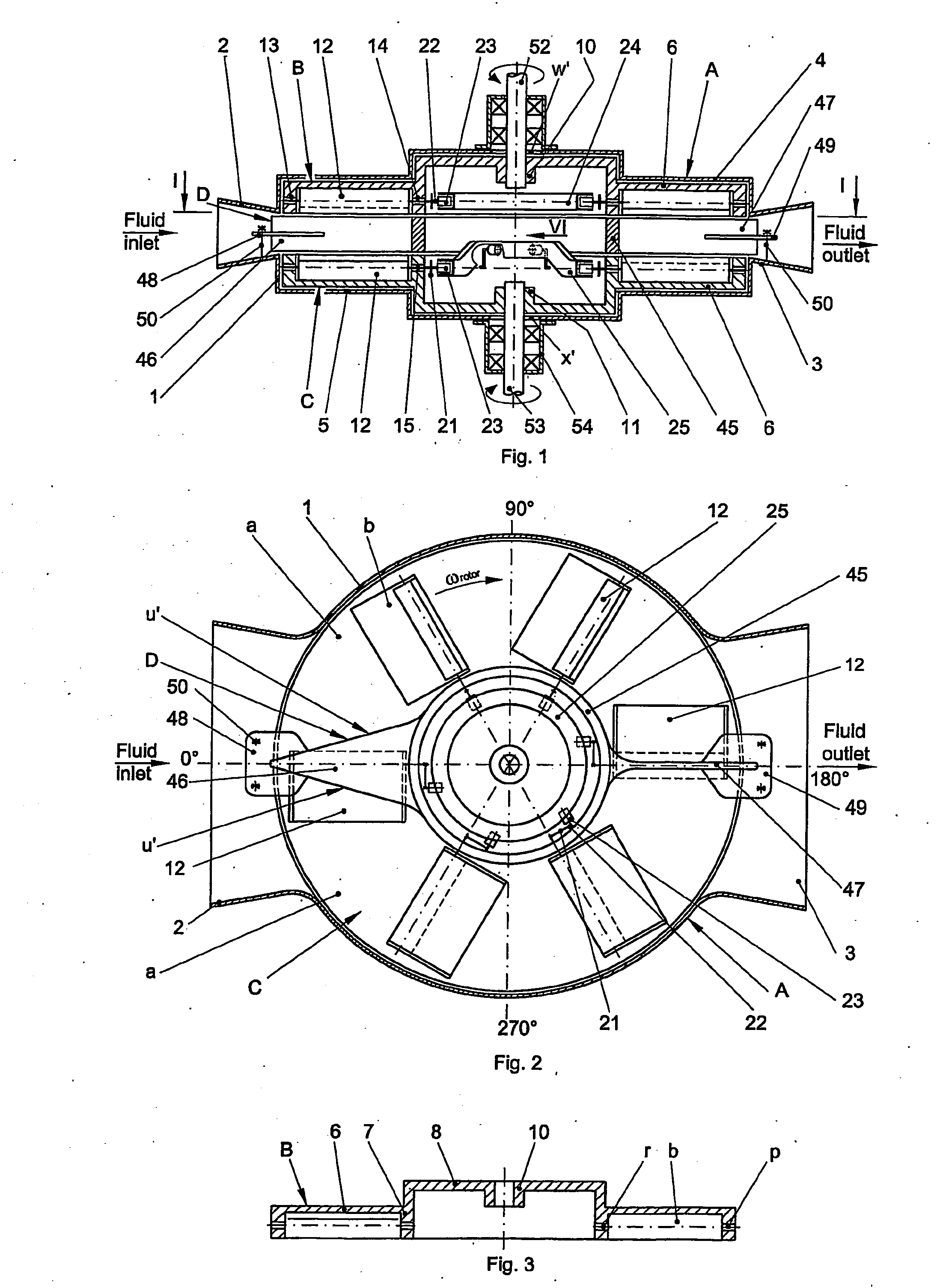
[0104] The hydraulic or pneumatic machine with vertical shaft made according to the invention consists of a fixed stator A, two disk like rotors, an upper one B and a lower one C, spaced from one another by a drum D connected onto stator A, all elements being in line, the parallel front faces of the two rotors being equipped with tilting blades which, due to some driving mechanisms of their own, can take against the rotor either a passive position—the blade in the front plane of the rotor, or an active position—the blade inclined by an α≦90° angle against the front face of said rotor. Inside the machine, two symmetrical, semicircular channels a are formed and due to the manner the driving mechanisms are arranged within the machine, the blades of one rotor are in active position, obstructing the passage of respective channel while the blades of the other rotor are in passive position, so that the circulating fluid along the two channels a flowing to the same sense, actuates the blade...

example 2

[0160] The hydraulic or pneumatic machine with vertical shaft, with multistage channels, made according to the invention, allows the circulation of a larger fluid flow, as compared to the one in the preceding example, by increasing the fluid passage section due to the use of several rotors of same diameter, namely: two extreme rotors with one front face each, provided with tilting blades 12, of which one, either the upper rotor B or the lower rotor C is mounted on one of the machine shafts and the other, a ring rotor E without supporting elements on machine shaft, and a number of disk F or ring G intermediate rotors with two front faces each, provided with tilting blades 12 on both faces, the blades on one face being mirror like arranged to those on the other face, their size and number being the same for the front faces of the rotors on each stage while they can vary from one stage to the other.

[0161] The tilting blades 12 of each rotor are arranged in such a manner as the neighbo...

example 3

[0201] The hydraulic or pneumatic machine with tilting blades, according to the invention, for working fluids under static pressure.

[0202] In view of adjusting the machine to run as a hydraulic or pneumatic motor using a working fluid under static pressure, in the circular space between the cylindrical shell 1 of stator A and the cylindrical body 45 of drum D, interdependent to it, is fixed a cylindrical ring 92 with the height corresponding to the distance between the front surfaces of rotors B, C, having on each front face of it a channel a″ of variable depth, for the action of the tilting blades 12 of the rotor close to said surface, the two channels connecting the fluid inlet and outlet nozzle, diametrically opposed, each having an initial zone b″, with a depth increasing to the rotation sense of said rotor, on the angular sector γ1 specific to blade transition from passive to active position, a middle zone c″ open to the other rotor, with constant depth, equal to the height of...


PUM


Abstract

This invention refers to a hydraulic or pneumatic machine with tilting blades, running either as an engine on a fluid flow or on pressure fluid or as a pump or a compressor. The hydraulic or pneumatic machine on a fluid flow according to the invention consists of a cylindrical casing with inlet and outlet openings, radially arranged, diametrically oposed, along the fluid flowing direction, some disk like rotors with tilting blades, hinged over their front faces and provided with driving mechanisms of their own, and some fixed drums located between the rotors, concentrically to them, making inside the machine some channels, symetrically arranged on one or several stages. Flowing through the channels, the fluid drives the tilting blades causing the movement of the rotors, all the rotors moving to one sense being coupled to the same outlet shaft of the machine. The tilting blades of the hydraulic or pneumatic machine operating according to the invention with pressure fluid, run in variable depth grooves located in the rings between the front faces of the rotors and connected to the fluid circuit, the operation conditions of the machine—motor or pump—being determined by the moving sense of the blade in the groove.

Description

TECHNICAL FIELD OF THEE INVENTION [0001] The invention pertains to a hydraulic or pneumatic machine with tilting blades in simple and solid construction which can be built in various constructional variants, meant to run with high efficiency as an engine fed by a fluid stream, pressure stream or pressure gases resulted from fuel combustion or as a pump or compressor with a broad range of industrial applications. BACKGROUND OF THE INVENTION [0002] There is a large variety of hydraulic or pneumatic machines having the rotor equipped with swinging or tilting blades round a fixed shaft on the rotor parallel or perpendicularly to its rotation axis driven by its own weight, by the centrifugal force or by its own driving mechanisms. During a full rotor rotation, the blades are putting up the maximum resistance to the motion to the fluid stream sense taking over part of its energy and the minimum resistance to the motion to the opposite sense of the fluid stream. [0003] Such machines have t...

Claims


Application Information

Patent Timeline
IPC IPC(8): B64C11/28F01C3/02
CPCF01C3/02F04D29/323F04D29/362
Inventor HOLT, CORNELIU
Owner HOLT CORNELIU
Why Eureka
Try Eureka