Hinged ankle brace

Active Publication Date: 2006-04-20
DJO
View PDF58 Cites 148 Cited by
  • Summary
  • Abstract
  • Description
  • Claims
  • Application Information

AI Technical Summary

Problems solved by technology

This ankle brace is, however, susceptible to modifications and altern

Method used


Image

  • Hinged ankle brace
  • Hinged ankle brace
  • Hinged ankle brace

Examples


Embodiment Construction

,” one will understand how the features of the preferred embodiments provide advantages, which include support for high ankle sprains, improved inversion and eversion control, reduced foot slippage, calcaneus support, and incremental adjustability as well as enhanced comfort, support and stability for a wearer.

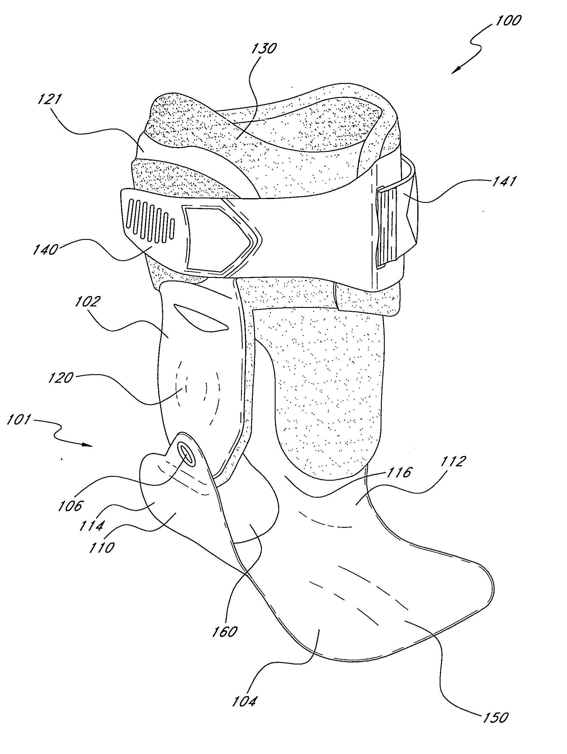
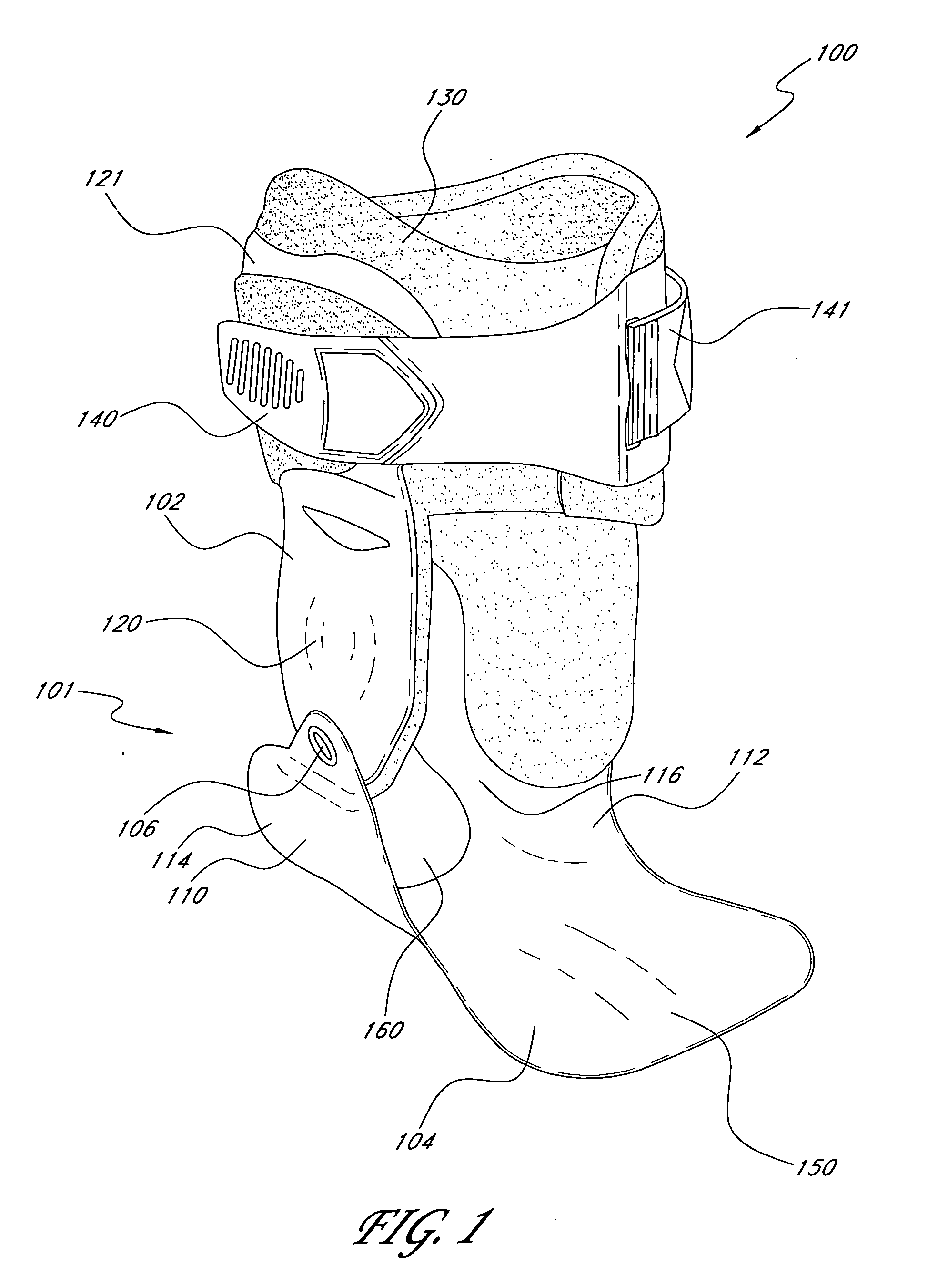
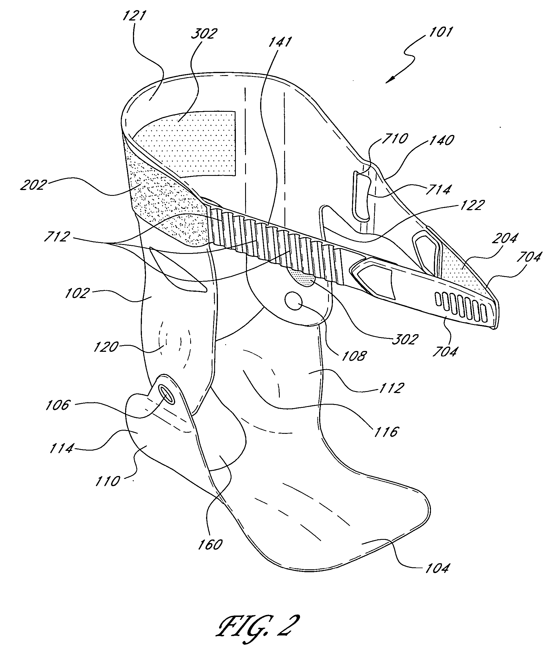
[0007] In certain embodiments, the present ankle braces comprise a semi-rigid ankle cuff, a semi rigid foot bed, a medial hinge, and a lateral hinge. The semi-rigid ankle cuff includes a calf-supporting portion configured to extend around a posterior side of a lower calf of a wearer, a medial upright extending generally downward from a medial side of the calf-supporting portion, and a lateral upright extending generally downward from a lateral side of the calf-supporting portion. The foot bed includes a foot plate contoured to underlie at least a portion of a foot of the wearer, a medial wing extending generally upward from the medial side of the foot bed, and a lateral wing e...


PUM


Abstract

A hinged ankle brace having a semi-rigid ankle cuff and a semi-rigid foot bed rotatably connected by a medial hinge and a lateral hinge provides enhanced stability and support to a wearer's ankle. The medial hinge of the ankle brace may be higher than the lateral hinge to accurately replicate the bending motion of an ankle. The ankle brace also includes ratchetably interconnected semi-rigid straps. These semi-rigid straps provide a semi-rigid structure encircling the ankle of a wearer for enhanced support. The ratchet mechanism may include a curved window that enables angular adjustment of the ratchting straps. The ankle brace may also include a soft inner liner and a soft outer sleeve. The outer sleeve is configured to provide compression to the semi-rigid shell, which in turn provides additional compression to the ankle. The semi-rigid foot bed may include posterior extensions that cup and support the wearer's heel, and a posterior cut-out portion that receives the wearer's heel.

Description

CROSS-REFERENCE TO RELATED APPLICATIONS [0001] This application claims priority to provisional application Ser. No. 60 / 615,621, filed on Oct. 4, 2004, the entire contents of which are hereby expressly incorporated by reference.BACKGROUND OF THE INVENTION [0002] 1. Field of the Invention [0003] The present invention relates to orthopedic ankle braces. [0004] 2. Description of the Related Art [0005] A variety of ankle braces are currently available to prevent ankle injuries, such as sprains. Some braces include purely soft components, and others incorporate rigid components. In general, these braces are designed to support the wearer's ankle and prevent unnatural movements that might cause injury. SUMMARY OF THE INVENTION [0006] The preferred embodiments of the present ankle braces have several features, no single one of which is solely responsible for their desirable attributes. Without limiting the scope of these ankle braces as expressed by the claims that follow, more prominent fe...

Claims


Application Information

Patent Timeline
IPC IPC(8): A61F5/00
CPCA61F5/0127A61F5/0111A61F2005/0137A61F2005/0172
Inventor VERKADE, DREW R.NATHANSON, JEREMYWALTERS, DAVID RODWELL II
Owner DJO
Why Eureka
Try Eureka