Formliner apparatus

a formliner and brick technology, applied in the field of formliner, can solve the problems of decorative bricks not being able to be made into regular brick walls, new type of technology was required, and the cost of brick and mortar walls has become relatively high, so as to reduce the chance of backing being dislodged during us

Active Publication Date: 2006-05-04
ARCHITECTURAL POLYMERS
View PDF34 Cites 37 Cited by
  • Summary
  • Abstract
  • Description
  • Claims
  • Application Information

AI Technical Summary

Benefits of technology

[0014] An advantage of the present invention is that the depth distances of at least substantially planar recess surfaces are varied, providing a brick veneer wall manufactured with the formliner of the present invention with the appearance of hand laid brick.
[0015] Another advantage of the present invention is that a brick veneer wall manufactured with the formliner of the present invention has a substantially seamless appearance of cementitious material after application without subsequent clean-up operation.
[0016] Another advantage of the present invention is that a backing is more firmly attached to a main section of a formliner, reducing the chances that the backing will be dislodged during use.

Problems solved by technology

However, making walls entirely of brick and mortar has become relatively expensive in recent years in comparison to poured concrete.
However, since decorative bricks cannot be made into a regular brick wall, a new type of technology was required.
Unfortunately, the clean and organized appearance of the final brick-lined concrete panel has resulted in an unforeseen aesthetic problem.
When cementitious material is applied to the surface of such joints, the cementitious material may flow through the planar joints, resulting in extra time and labor to clean up the cementitious material that flowed through the planar joints.
However, such plywood may become dislodged during the use of the formliner, particularly if the formliner is used numerous times.

Method used


Image

  • Formliner apparatus
  • Formliner apparatus
  • Formliner apparatus

Examples


Embodiment Construction

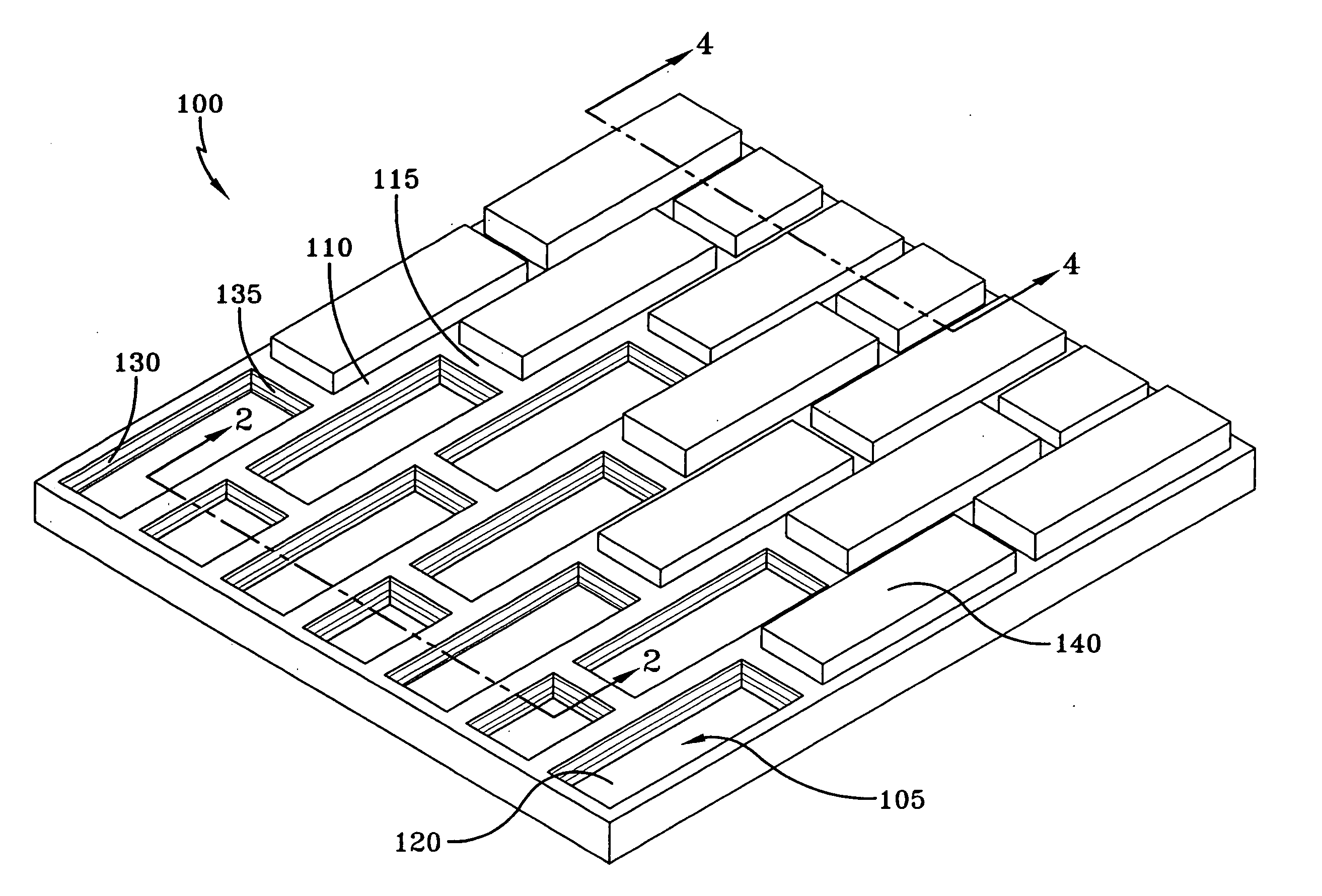
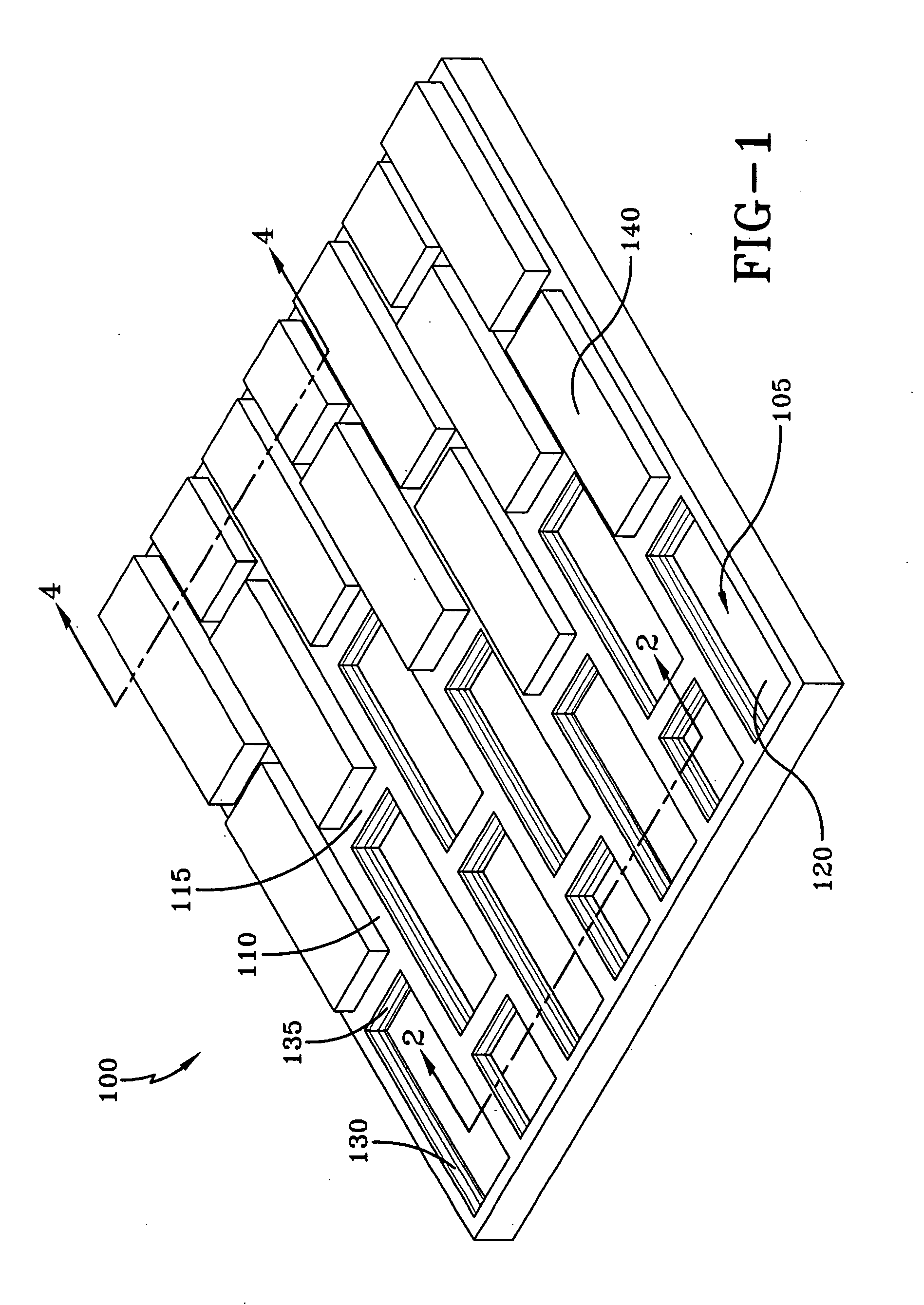
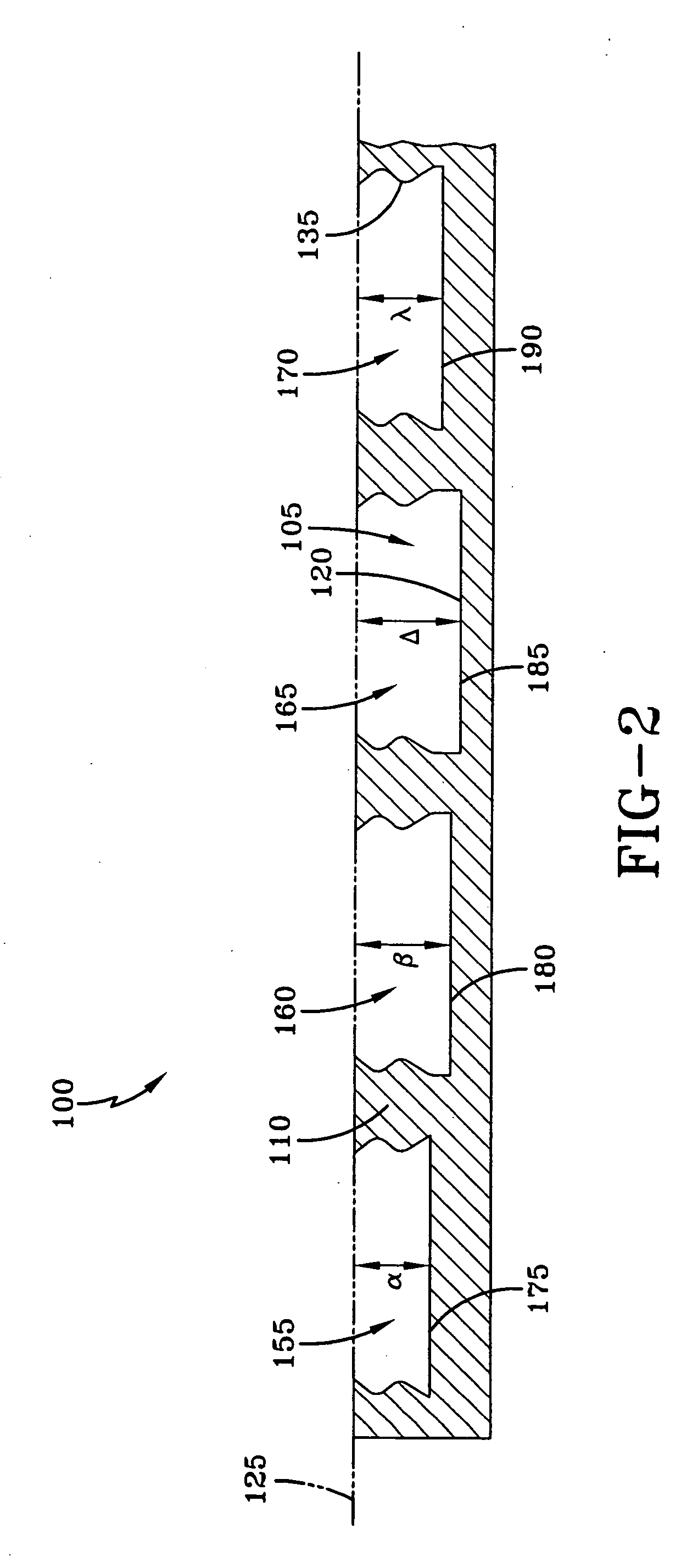
[0035] The present invention is a formliner apparatus, one embodiment of which is shown in FIG. 1. A brick formliner 100 is formed with a series of recesses 105, which are separated by and defined by lateral ribs 110 and interconnecting transverse ribs 115. The recesses 105 are shown in the figures in a brick running bond configuration, the configuration in which bricks are conventionally applied to walls. Such running bond configuration is only used to illustrate the features of the present invention and is not intended to limit the scope of the invention. Any other formliner configuration known in the art may also be used with the present invention, such as, for example flemish bond, basket weave, herringbone, etc. At the base of each recess 105 is an at least substantially planar recess surface 120. The lateral ribs 110 and transverse ribs 115 extend from the at least substantially planar recess surfaces 120 to a rib plane 125 (shown in FIG. 2). While the present invention is des...


PUM

PropertyMeasurementUnit
thicknessaaaaaaaaaa
thicknessaaaaaaaaaa
thicknessaaaaaaaaaa

Abstract

The present invention is a formliner apparatus comprising a plurality of substantially planar layers. The formliner further comprises a plurality of ribs extending in a direction away from the substantially planar layers and defining a plurality of recesses within the formliner in conjunction with the substantially planar layers, each of the plurality of ribs extending to a preselected rib plane. The present invention further comprises at least one resilient ridge on each rib defining each recess, each at least one resilient ridge extending into an adjacent recess, wherein each substantially planar layer is substantially parallel with the rib plane and located a preselected variance depth distance from the rib plane, each variance depth distance for at least some of the substantially planar layers being preselected from a preselected variance depth distance range, wherein each preselected variance depth distance not being equal to every other variance depth distance.

Description

CROSS-REFERENCE TO RELATED APPLICATIONS [0001] This application claims the benefit of U.S. Provisional Application No. 60 / 650,934, filed Feb. 8, 2005, entitled “FORMLINER APPARATUS,” which application is incorporated herein by reference in its entirety.FIELD OF THE INVENTION [0002] The present invention relates generally to formliners and, more particularly, to a brick formliner apparatus that uses substantially randomly positioned brick depths. BACKGROUND OF THE INVENTION [0003] Architectural designs for various types of construction, including buildings and bridges, call for the use of brick in the walls of buildings. Although of little structural importance in modern construction projects, brick walls continue to be used for decorative architectural purposes. However, making walls entirely of brick and mortar has become relatively expensive in recent years in comparison to poured concrete. One development that has reduced the cost of brick walls has been the use of decorative thi...

Claims


Application Information

Patent Timeline
Patent Type & Authority Applications(United States)
IPC IPC(8): E04G9/10E04G11/06
CPCE04G9/10B28B19/0061
Inventor WALTERS, MARSHALL GILBERT
Owner ARCHITECTURAL POLYMERS
Why Eureka
Try Eureka