
System and method for partitioning processor resources based on memory usage

a processor resource and memory usage technology, applied in the field of system and method for partitioning processor resources based on memory usage, can solve the problems of taking a prolonged amount of time to execute, compounding problems, and exacerbated challenges, and achieve the effect of masking the latency of the first thread's prolonged instruction

Inactive Publication Date: 2006-05-04
IBM CORP
View PDF4 Cites 58 Cited by
  • Summary
  • Abstract
  • Description
  • Claims
  • Application Information

AI Technical Summary

Benefits of technology

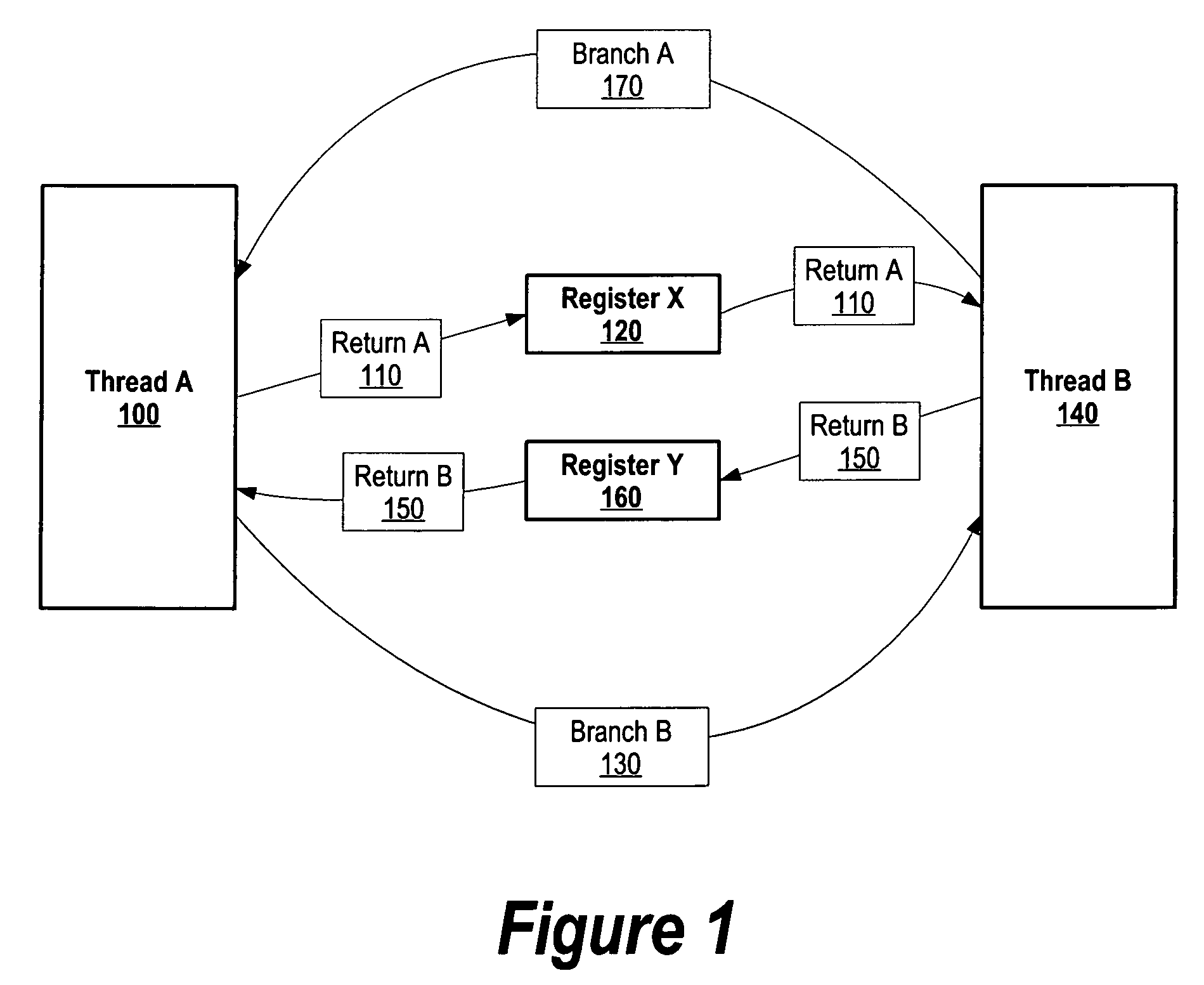
[0009] It has been discovered that the aforementioned challenges are resolved by passing control to a second thread while a first thread processes a prolonged instruction using branch instructions. At compile time, Branch Indirect and Set Link if External Data (BISLED) instructions are placed in thread code at instances that correspond to a thread's prolonged instruction. A prolonged instruction is an instruction that may instigate latency in a computer system, such as a DMA instruction. When a first thread encounters a BISLED instruction, the first thread passes control to a second thread while the first thread's prolonged instruction executes, thereby masking the latency of the first thread's prolonged instruction.

Problems solved by technology

There are instructions, however, that take a prolonged amount of time to execute.
A challenge found with prolonged instructions is removing the latency that results when an application waits for the prolonged instruction to finish.
A further challenge is found when an application invokes multiple threads and one of the threads encounters a prolonged instruction.
This challenge is exacerbated when an application is more memory-bound.
In memory-bound applications, the threads wait for each memory request, thus compounding the problem when numerous memory requests are performed.

Method used


Image

  • System and method for partitioning processor resources based on memory usage
  • System and method for partitioning processor resources based on memory usage
  • System and method for partitioning processor resources based on memory usage

Examples


Embodiment Construction

[0037] The following is intended to provide a detailed description of an example of the invention and should not be taken to be limiting of the invention itself. Rather, any number of variations may fall within the scope of the invention which is defined in the claims following the description.

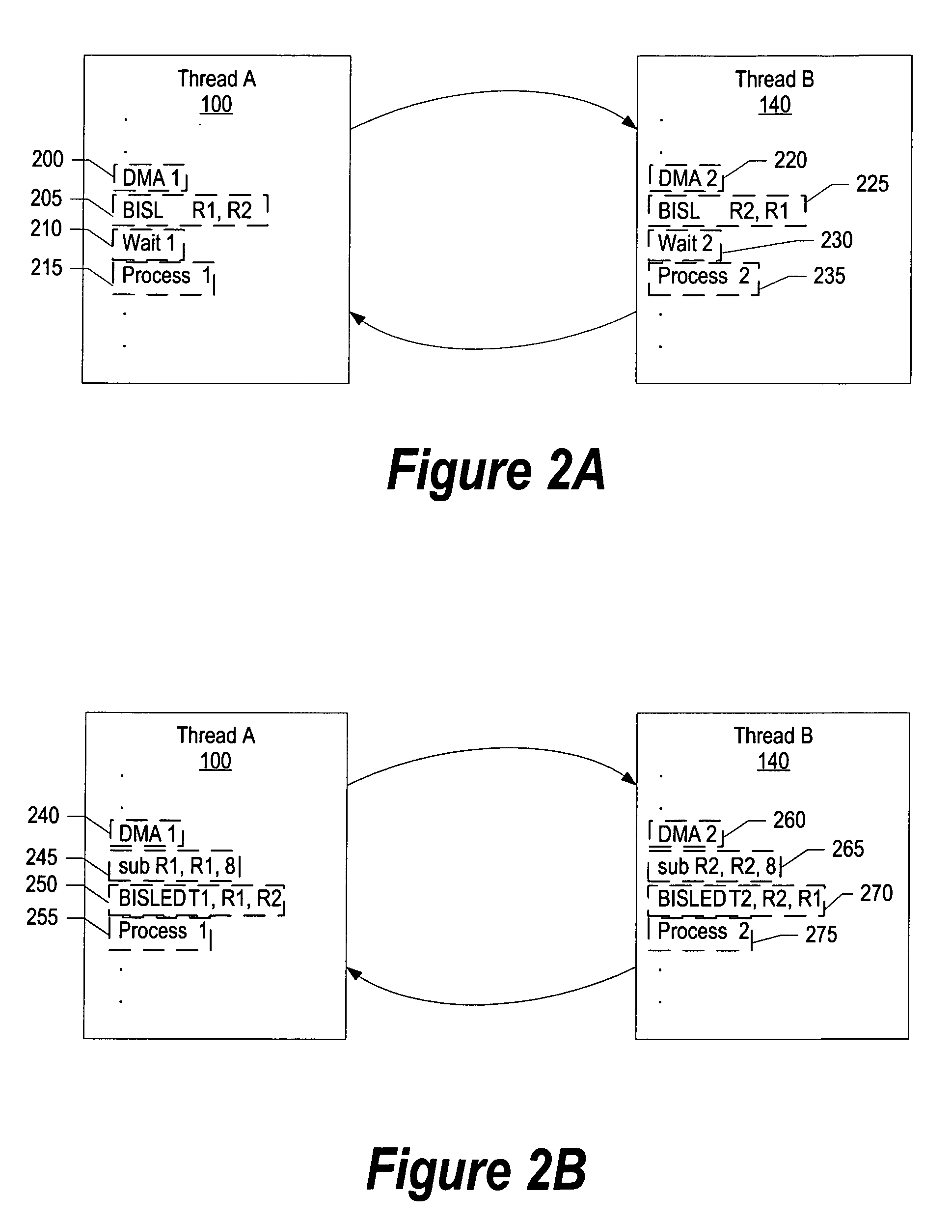
[0038]FIG. 1 is a diagram showing two threads branching to each other when the threads encounter a prolonged instruction. While the example shown in FIG. 1 includes two threads, the invention described herein is not limited to two threads and, as one skilled in the art can appreciate, the invention is applicable to any number of multiple threads. At compile time, Branch Indirect and Set Link (BISL) and / or Branch Indirect and Set Link if External Data (BISLED) instructions are placed in thread code at instances that correspond to a thread's prolonged instruction. A prolonged instruction is an instruction that may instigate latency in a computer system, such as a DMA instruction. When a first t...


PUM


Abstract

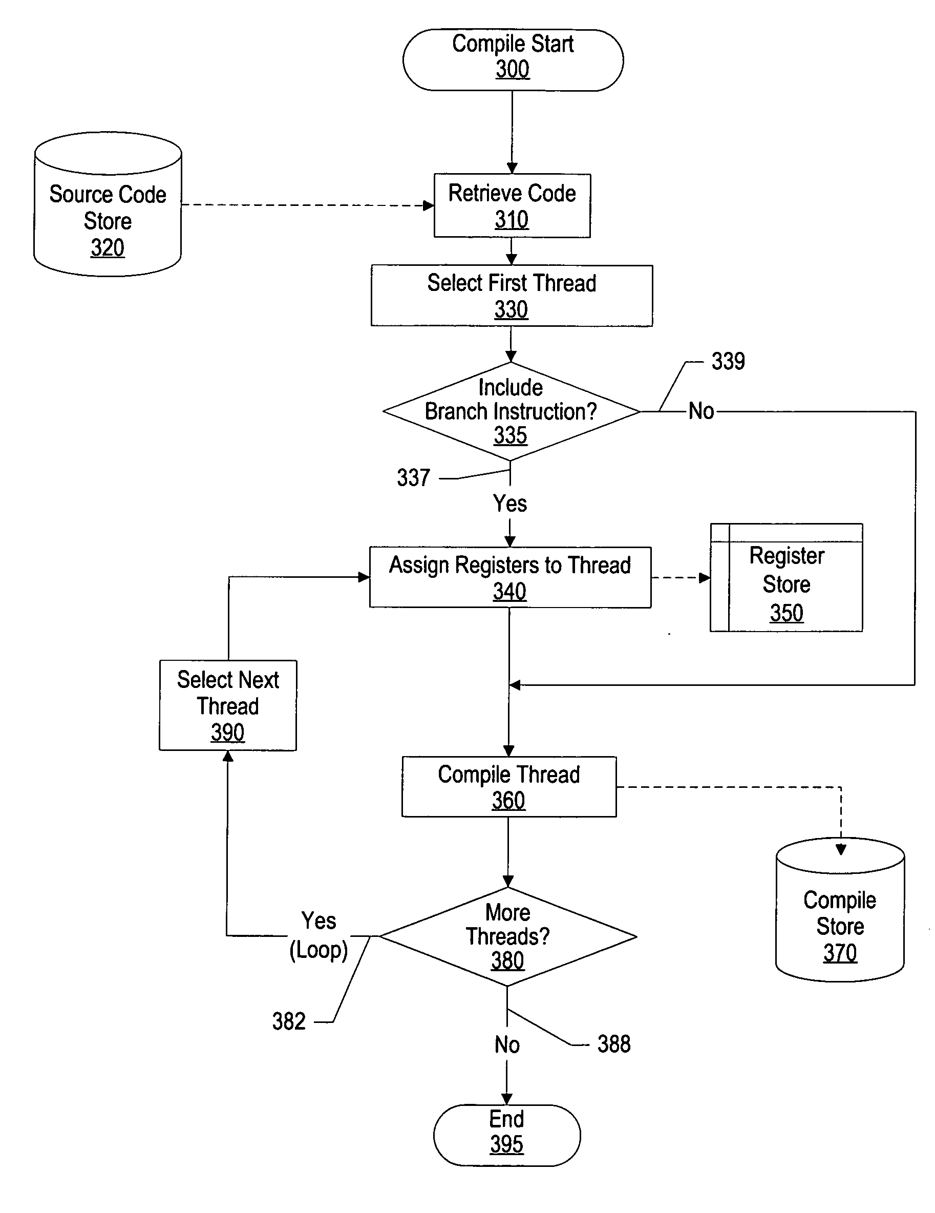
A system and method for partitioning processor resources based on memory usage is provided. A compiler determines the extent to which a process is memory-bound and accordingly divides the process into a number of threads. When a first thread encounters a prolonged instruction, the compiler inserts a conditional branch to a second thread. When the second thread encounters a prolonged instruction, a conditional branch to a third thread is executed. This continues until the last thread conditionally branches back to the first thread. An indirect segmented register file is used so that the “return to” and “branch to” logical registers within each thread are the same (e.g., R1 and R2) for each thread. These logical registers are mapped to hardware registers that store actual addresses. The indirect mapping is altered to bypass completed threads. When the last thread completes it may signal an external process.

Description

RELATED APPLICATIONS [0001] This application is a continuation-in-part of commonly assigned, co-pending U.S. Non-Provisional patent application Ser. No. 10 / 960,609, entitled “SYSTEM AND METHOD FOR HIDING MEMORY LATENCY,” filing date Oct. 7, 2004, Attorney Docket No. AUS920040161US1, which is incorporated herein by reference.BACKGROUND OF THE INVENTION [0002] 1. Technical Field [0003] The present invention relates in general to a system and method for partitioning processor resources based on memory usage. More particularly, the present invention relates to a system and method for, in a multi-thread environment, automatically create additional threads in memory-bound processes in order to reduce memory latency. [0004] 2. Description of the Related Art [0005] Developers attempt to increase a computer system's performance by improving both the hardware aspects and the software aspects of the computer system. From a hardware perspective, a hardware developer may focus on improving areas...

Claims


Application Information

Patent Timeline
Patent Type & Authority Applications(United States)
IPC IPC(8): G06F9/45
CPCG06F8/41G06F9/322G06F9/3851G06F8/451G06F9/5016G06F9/5061
Inventor BROKENSHIRE, DANIEL ALANMINOR, BARRY L.NUTTER, MARK RICHARD
Owner IBM CORP
Learn More