Roof venting system

a venting system and roof technology, applied in ventilation systems, lighting and heating apparatus, heating types, etc., can solve the problems of insufficient strength, troublesome shortcomings, early deterioration, etc., to facilitate the slope, inhibit the inward passage of moisture and insects, and enhance the outward flow of air.

Inactive Publication Date: 2006-05-11
PAVLANSKY MARK +1
View PDF20 Cites 35 Cited by
  • Summary
  • Abstract
  • Description
  • Claims
  • Application Information

AI Technical Summary

Benefits of technology

[0008] Another objective of the present invention is to enhance the outward flow of air from the region beneath the roof and at the same time inhibit the inward passage of moisture and insects.
[0009] Yet another objective of the present invention to provide a vent cover which engages a pair of laterally spaced open cell members so that air can freely flow outwardly therethrough while the entry of moisture and insects in a reverse direction is inhibited.
[0010] Still another objective of the present invention to provide foam members having a multiplicity of interconnected open pores so that maximu

Problems solved by technology

While this material solved numerous problems, it still had several troubling shortcomings such as shrinkage, early deterioration, insufficient strength, low ultraviolet resistance, low tear resistance, density and low fire retardancy.
Different materials were tested, but no acceptable version was identified until a few years ago when it was determi

Method used


Image

  • Roof venting system
  • Roof venting system
  • Roof venting system

Examples


Embodiment Construction

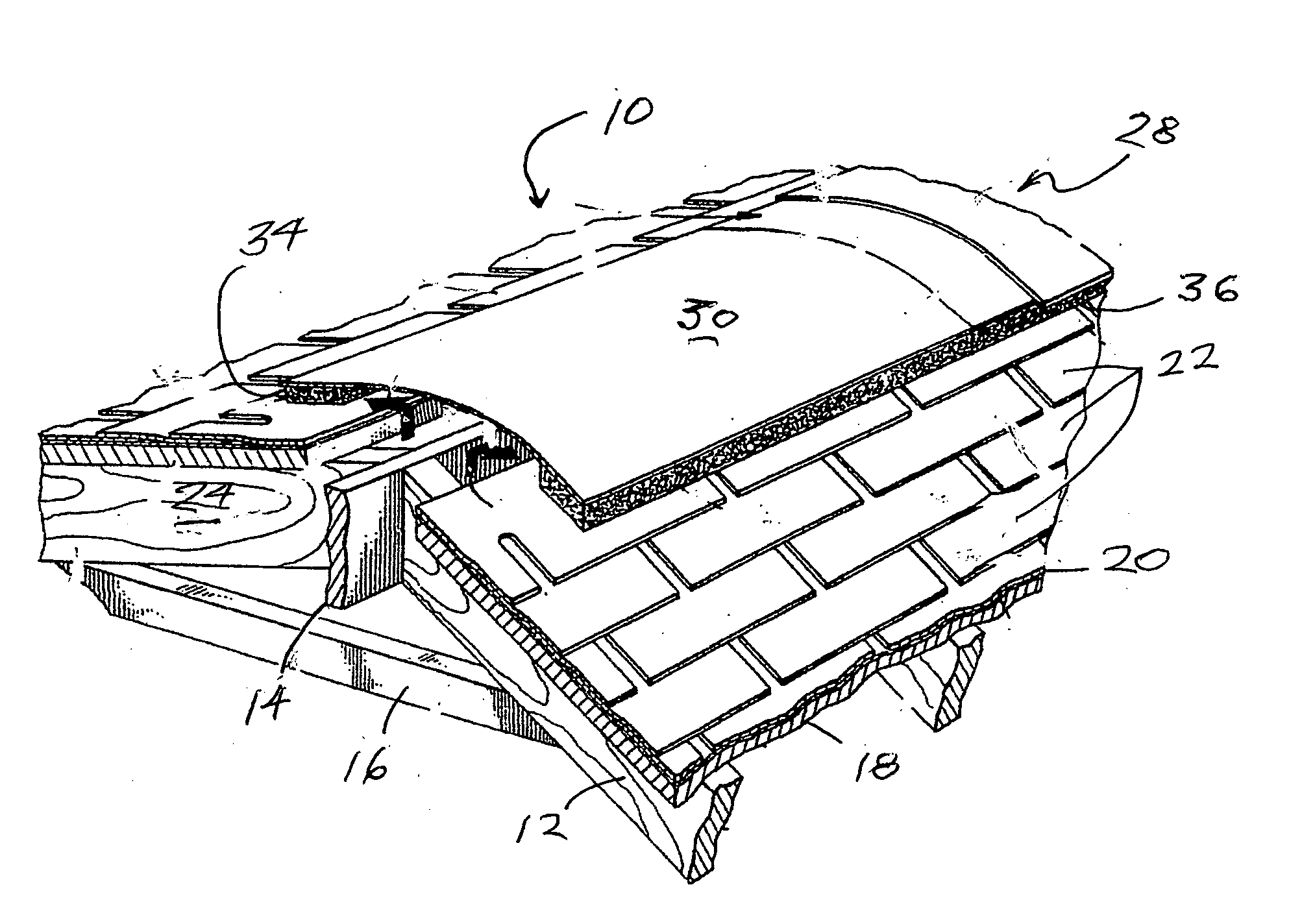
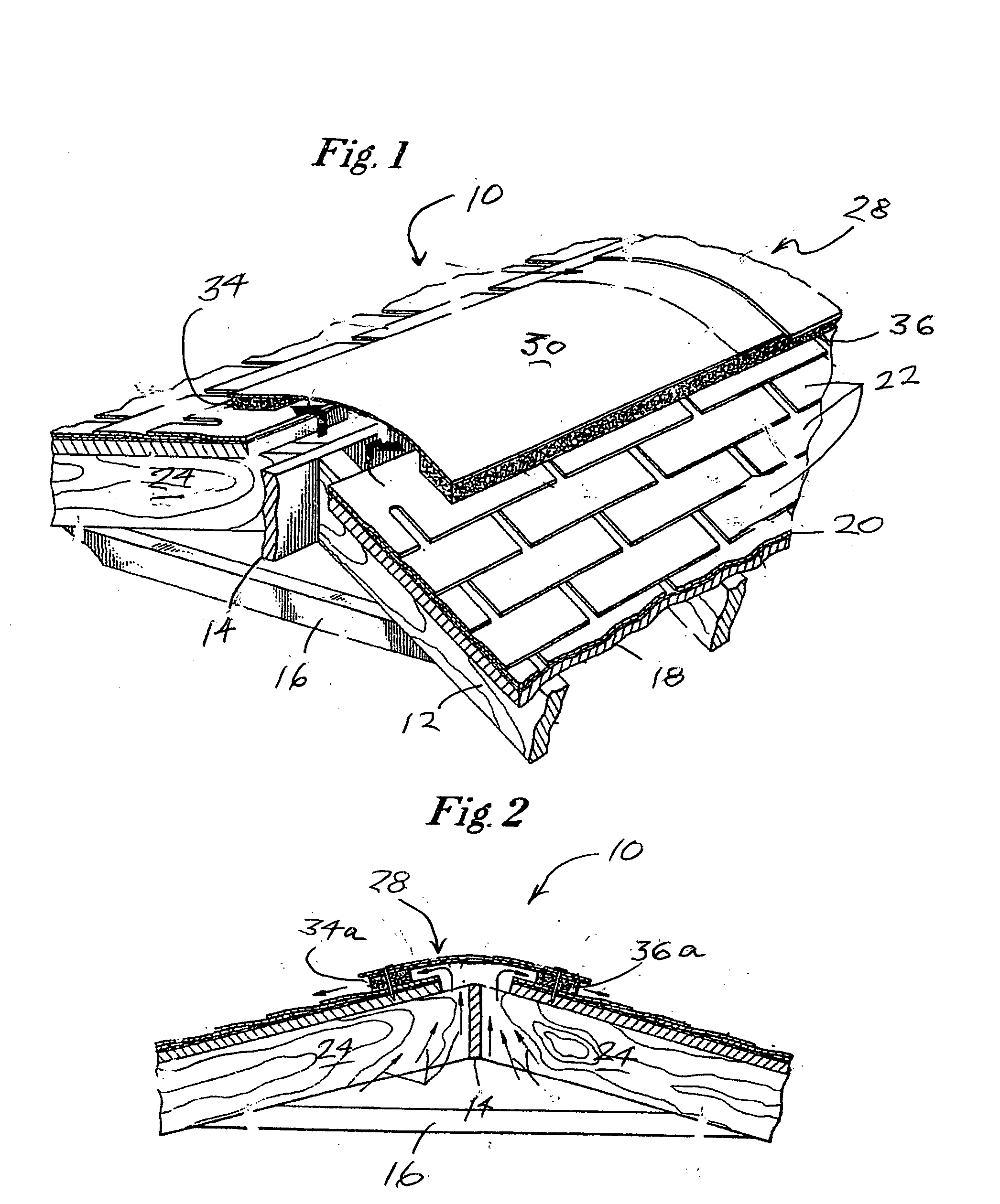
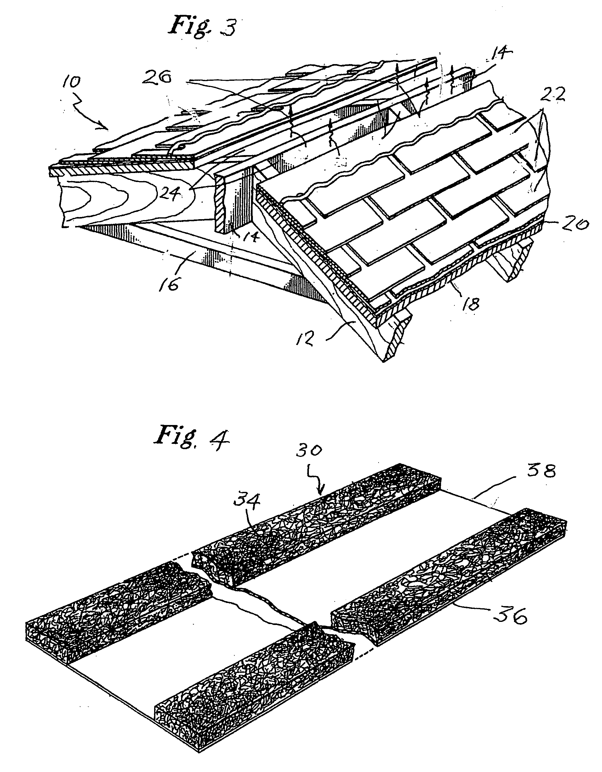
[0034] The present invention is more conveniently used with conventional sloping roofs such as are shown in FIGS. 1, 2 and 3 wherein a portion of one such roof shown generally as 10 includes rafters 12 and a ridge member 14 placed within the upper ends of rafters 12 and a collar beam 16 extending horizontally between each pair of rafters. Some roofs employ a truss construction not requiring a ridge member, and this roof is equally compatible with the invention. Sheathing 18 overlies rafters 12, and over sheathing 18 is placed a layer of felt or building paper 20. Roof shingles 22 are nailed through the felt 20 into sheathing 18. A vent opening 24 permits the upward and outward flow of air in the direction of the arrows 26 (FIG. 3) from the region beneath roof 10 such as an attic. Various vents (not shown) in the lower portion of the attic permit the ingress of air so that normal airflow is upwardly and outwardly through vent opening 24 as indicated by arrows 26.

[0035] The primary e...


PUM


Abstract

A roof venting system for removing warm and moist air from the interior of a building to the outside through a vent opening in the roof. The system includes a vent, cover member for placement over the vent opening and two foam members through which the indoor warm and moist air must pass when the air flows from the building interior to the outside. The foam members may be provided with a convoluted surface to facilitate close engagement to the roof profile, and a single piece foam may be used instead of the usual two. The foam and cover members may be flexible, reticulated polyurethane treated with one or more substances to enhance fire resistance and protect from heat/cold adverse weather.

Description

BACKGROUND OF THE INVENTION [0001] 1. Field of the Invention [0002] The present invention relates to metal roof systems and shingle roof systems that are used in both commercial and residential buildings and, more particularly, to vent coverings which allow for airflow and prevent foreign contaminants such as insects, birds, small animals and excess water from entering a roofing system by forming a partial seal. [0003] 2. Description of the Prior Art [0004] The life span of any roof will be increased if adequate ventilation is provided along the top vent of the roof. Ventilation is needed to allow air to flow through and out of the roof interior and out of the vent which is located along the top of the roof where the two slopes of the roof nearly meet. Having adequate airflow that uses roof ventilation is a proven construction technique that is used in both new construction and remodeling existing structures. Ventilation of the roof has been historically accomplished through the use...

Claims


Application Information

Patent Timeline
IPC IPC(8): E04B7/00
CPCE04D13/174F24F7/02
Inventor PAVLANSKY, MARKPAVLANSKY, KEITH
Owner PAVLANSKY MARK
Why Eureka
Try Eureka