
Yarn manufacturing apparatus and method

a manufacturing apparatus and yarn technology, applied in the field of yarns, can solve the problems of reducing the air pressure of the entangling jet, affecting the quality of the yarn, so as to achieve the effect of enhancing the color pop

Active Publication Date: 2006-05-11
COLUMBIA INSURANCE CO
View PDF68 Cites 7 Cited by
  • Summary
  • Abstract
  • Description
  • Claims
  • Application Information

AI Technical Summary

Benefits of technology

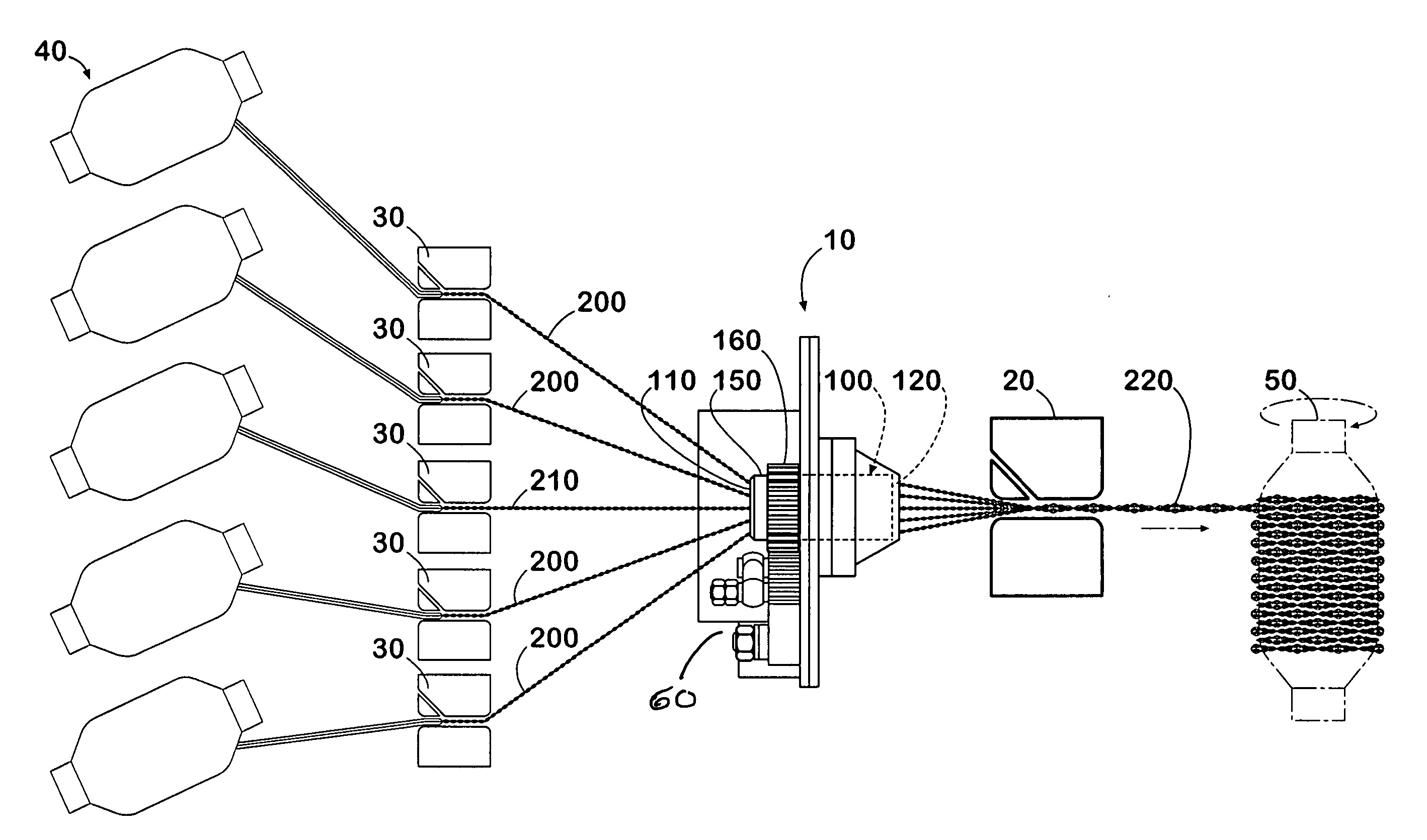
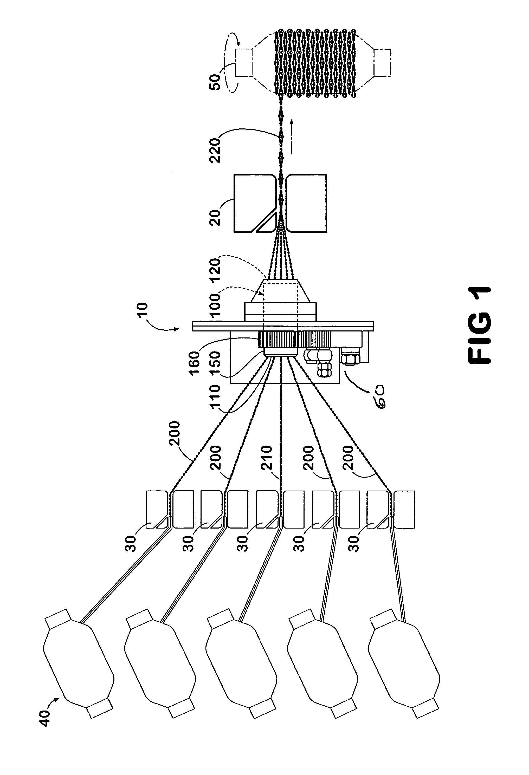
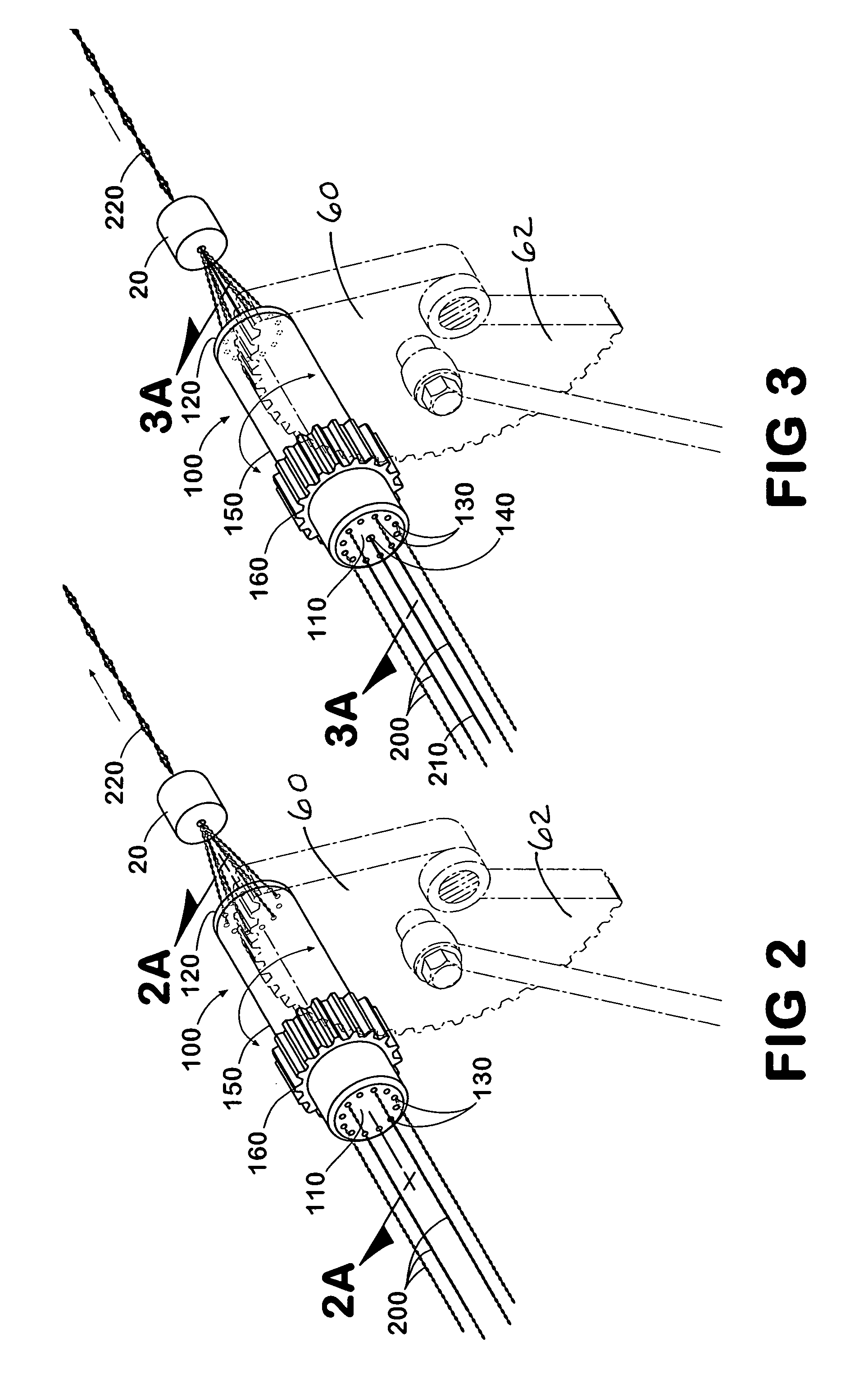
[0005] The present invention addresses the problems in the art and minimizes streaking when a large denier yarn is tufted into a carpet. Additionally, it provides an apparatus and method of making yarn for carpet that exhibits a high degree of color pop. More specifically, in one aspect, the present invention comprises a yarn manufacturing apparatus and method that comprises supplying a plurality of yarns, false-twist the plurality of yarns, and passing the consolidated yarn through a first entangling assembly to tack at least a portion of the consolidated yarn. In another aspect, the invention comprises passing at least one of the plurality of yarns through one or more second entangling assemblies upstream of the false-twist apparatus.
[0006] False-twisting the yarns prior entangling them into a consolidated yarn enhances color pop in the resulting consolidated yarn by changing the order that the yarns are fed into the first entangling assembly. Constantly changing the feed order of the yarns into the first entangling assembly reduces the possibility of one yarn riding on top of the others.

Problems solved by technology

One of the main issues with this process is that it is difficult to obtain a good quality yarn with a high degree of color pop.
When the air pressure of the entangling jets is sufficient enough to impart substantially uniformly spaced bulked portions and tacks, the colors of the individual yarns may be muted and lose their individual characteristics.
On the other hand, if a high degree of color pop is desired, the air pressure of the entangling jets would be reduced, thereby not allowing the individual yarns to get overly entangled.
Constantly changing the feed order of the yarns into the first entangling assembly reduces the possibility of one yarn riding on top of the others.

Method used


Image

  • Yarn manufacturing apparatus and method
  • Yarn manufacturing apparatus and method
  • Yarn manufacturing apparatus and method

Examples


Embodiment Construction

[0017] The present invention is more particularly described in the following exemplary embodiments that are intended as illustrative only since numerous modifications and variations therein will be apparent to those skilled in the art. As used herein, “a,”“an,” or “the” can mean one or more, depending upon the context in which it is used. The preferred embodiments are now described with reference to the figures, in which like reference characters indicate like parts throughout the several views.

[0018] Ranges may be expressed herein as from “about” one particular value, and / or to “about” another particular value. When such a range is expressed, another embodiment includes from the one particular value and / or to the other particular value. Similarly, when values are expressed as approximations, by use of the antecedent “about,” it will be understood that the particular value forms another embodiment.

[0019] In one aspect, the present invention provides a continuous yarn manufacturing...


PUM

PropertyMeasurementUnit
Fractionaaaaaaaaaa
Fractionaaaaaaaaaa
Fractionaaaaaaaaaa

Abstract

The present invention is an apparatus and method of making yarn for carpet that exhibits a high degree of color pop. More specifically, in one aspect, the present invention comprises an apparatus and method that comprises supplying a plurality of yarns, false-twist the plurality of yarns, and passing the consolidated yarn through a downstream entangling assembly to tack at least a portion of the consolidated yarn. Another aspect of the present invention passes at least one of the plurality of yarns through one of a plurality of second entangling assemblies positioned upstream of the false-twist apparatus.

Description

FIELD OF THE INVENTION [0001] The present invention pertains to the field of continuous synthetic filaments, and particularly, to yarns comprised of multiple continuous filaments. In some embodiments, the present invention pertains to yarns suitable for the production of carpets. BACKGROUND OF INVENTION [0002] Carpet manufacturers are continually searching for yarns which provide distinct visual appearance when converted into cut, loop pile or cut-loop pile carpet structures. For example, continuous filament carpet yarns which provide an appearance to the final carpet structure showing distinct and separate colors have achieved widespread popularity. The distinct appearance of different colors in the carpet is commonly referred to as “color pop.”[0003] One of the main issues with this process is that it is difficult to obtain a good quality yarn with a high degree of color pop. When the air pressure of the entangling jets is sufficient enough to impart substantially uniformly spaced...

Claims


Application Information

Patent Timeline
IPC IPC(8): D02G3/36D02G3/02
CPCD01H7/90D01H7/92D02G1/0206D02G1/0226D02G1/024D02G3/445D02J1/08
Inventor KEITH, KENNETH H.
Owner COLUMBIA INSURANCE CO
Learn More