Arthroplasty implant

a technology of implant and lateral separation, applied in the field of arthroplasty implants, can solve the problems of limiting the flexibility of the intermediate, the load-transmitting ability or life expectancy, etc., and achieve the effect of preventing lateral separation and preventing lateral separation

Inactive Publication Date: 2006-05-11
DE VILLIERS MALAN
View PDF5 Cites 55 Cited by
  • Summary
  • Abstract
  • Description
  • Claims
  • Application Information

AI Technical Summary

Benefits of technology

[0012] In another embodiment of the invention one of the first component and the intermediate component includes a laterally outwardly facing projection and the other of the first component and the intermediate component includes a laterally inwardly facing recess, the projection in use interacting with the recess to prevent lateral separation of the intermediate and first components. Typically in this embodiment, the first component includes an annular wall bounding the concave surface of that component, the peripheral wall being formed with an annular undercut defining the laterally inwardly facing recess, and the intermediate component includes an annular rib defining the laterally outwardly facing projection, interaction in use between the rib and the undercut preventing lateral separation of the intermediate and first components.

Problems solved by technology

It is however believed that the known implants, most of which are of two part construction, suffer from one disadvantage or other that either limits their flexibility, load-transmitting ability or life expectancy.

Method used


Image

  • Arthroplasty implant
  • Arthroplasty implant
  • Arthroplasty implant

Examples


first embodiment

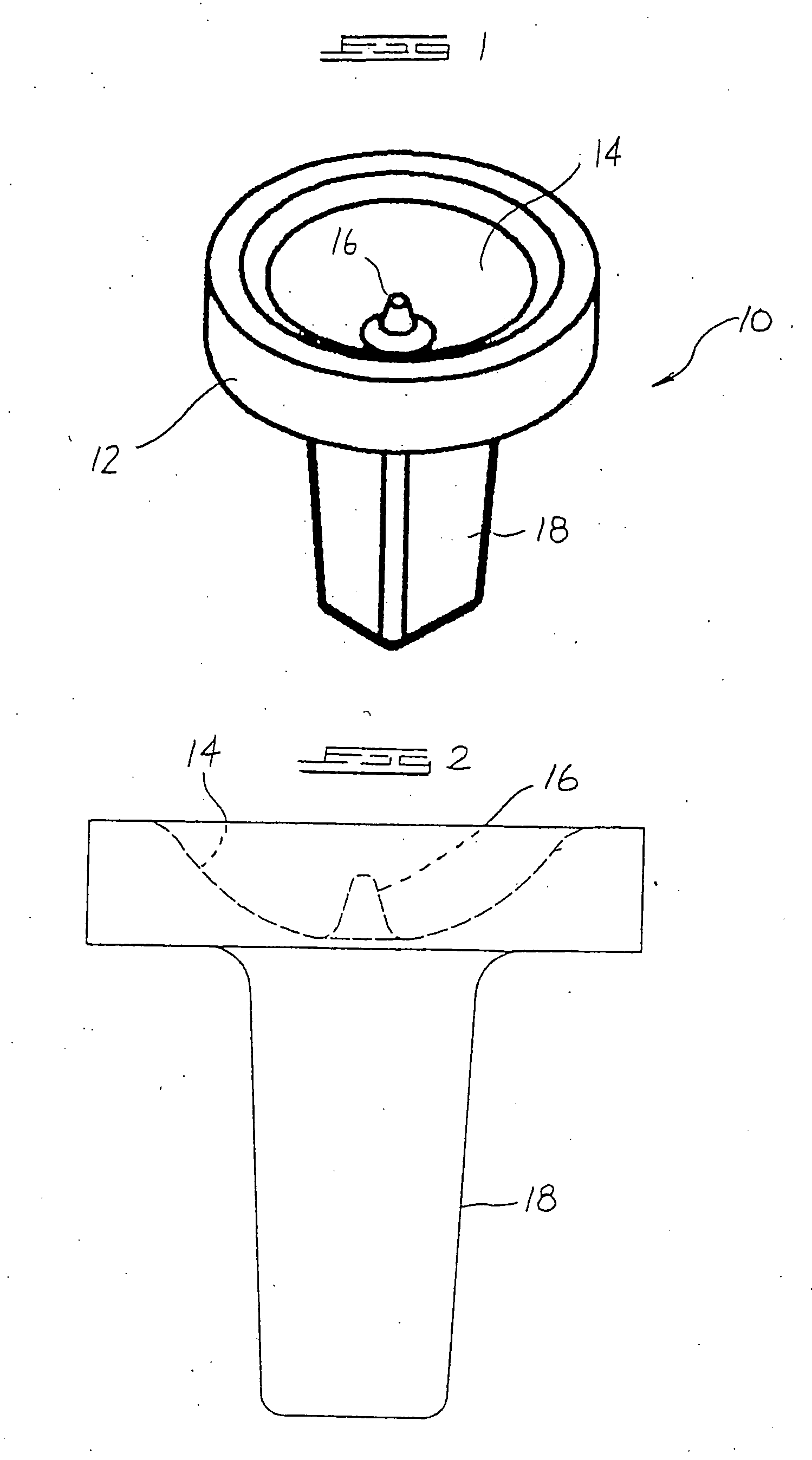
[0035] the invention is illustrated in FIGS. 1 to 12 of the drawings. In this embodiment, FIGS. 1 and 2 illustrate a first, phalangeal component 10 which is connected in use to a phalanx. It includes a body 12 formed with a spherically curved, concave surface 14. Projecting centrally from the surface 14 is a conical peg 16 and projecting rearwardly from the body 12 is a tapered post 18 of square cross-section. In use, the post 18 is placed and anchored in a predrilled hole in the phalanx.

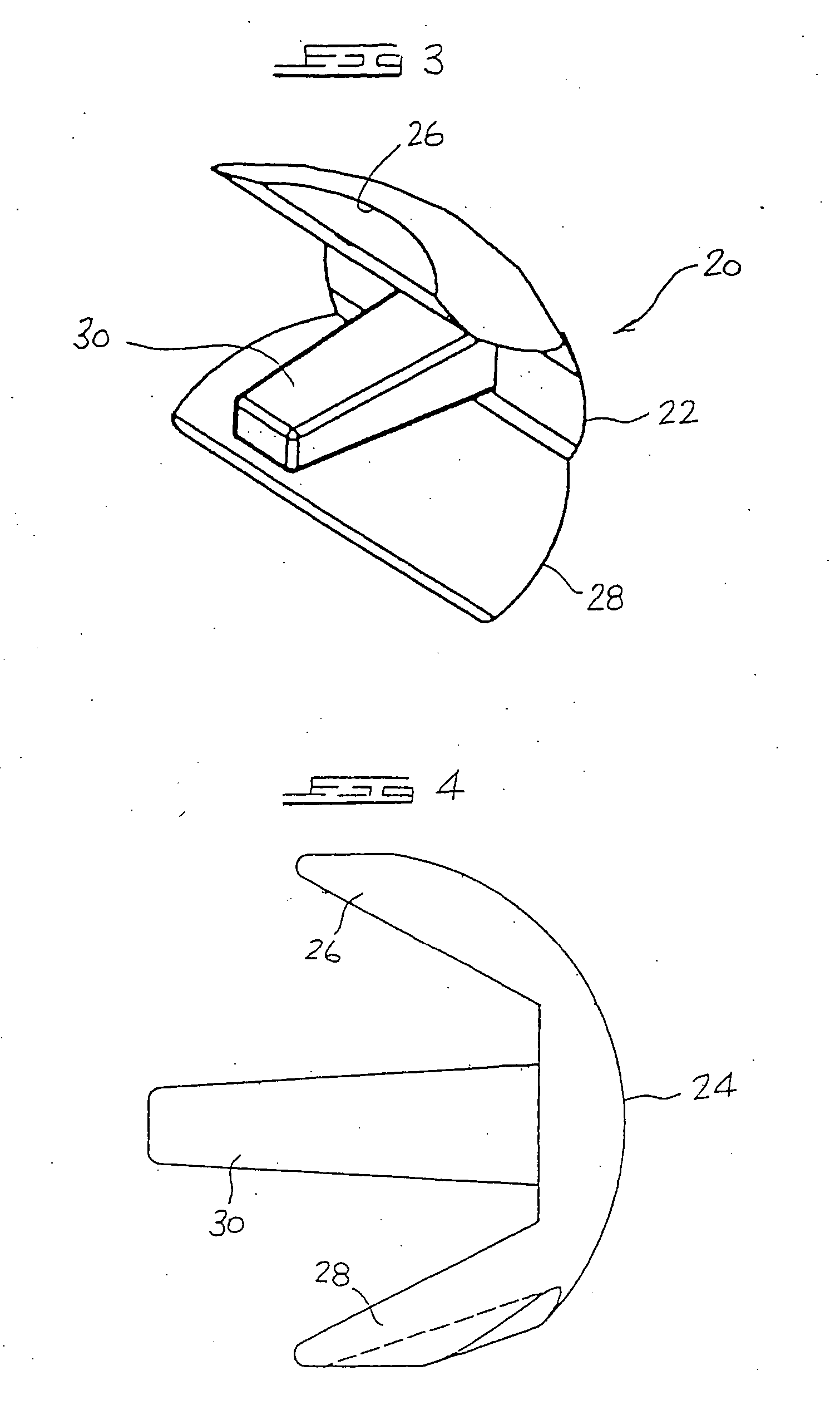
[0036] FIGS. 3 to 5 illustrate a second, tarsal component 20 which is connected in use to the associated tarsus. It includes a body 22 with a convexly curved surface 24 and curved skirts 26, 28. The radius of curvature of the surface 24 in the view of FIG. 4 is less than the radius of curvature in the view of FIG. 5. Projecting rearwardly from the body 22 is a tapered post 30 of square cross-section. In use the post 30 is placed and anchored in a predrilled hole in the tarsus.

[0037] Both the phalan...

second embodiment

[0043] the invention is illustrated in FIGS. 13 to 19 of the drawings. In these Figures features corresponding to features seen in FIGS. 1 to 12 are indicated by the same reference numerals.

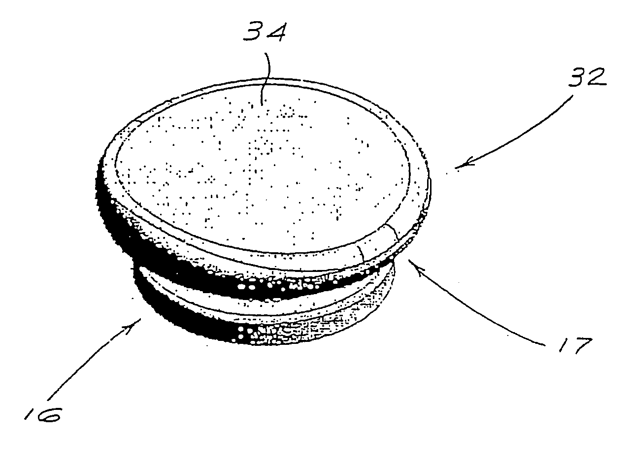
[0044] Notable differences between the first or phalangeal component 10 illustrated in FIGS. 13 and 14 and the first component 10 seen in FIGS. 1 and 2 are the absence of the central peg 16 and the inclusion of an annular, peripheral wall 52 which bounds the concave surface 14 and which is formed with an undercut 50 defining a laterally inwardly facing recess. The wall 52 and concave surface in combination define a cup-shaped receptacle 53.

[0045] Another difference between the component 10 of FIGS. 13 and 14 and that of FIGS. 1 and 2 is the face that the post 18 has a round cross-section and is provided at its end with barb formations 54.

[0046] The second or tarsal component 20 of the second embodiment is seen in FIGS. 18 and 19. This component differs from the second component illustrated in F...


PUM

PropertyMeasurementUnit
radii of curvatureaaaaaaaaaa
lengthaaaaaaaaaa
frictionaaaaaaaaaa

Abstract

The invention concerns an arthroplasty implant for providing a joint between first and second members of the body, such as a metatarsophalangeal (MTP) joint, a metacarpophalangeal (MCP) joint or a proximal interphalangeal (PIP) joint. The implant of the invention includes a fist component (10) defining a concave surface (14), a second component (20) defining a convex surface (24) and an intermediate component (32) which is located between the first and second components. The intermediate component has a convex surface (36) which is slidable on the concave surface of the first component to allow articulation between the first component and the intermediate component and a concave surface slidable on the convex surface of the second component to allow articulation between the second component and the intermediate component. A means (16, 38; 50, 60) is provided to prevent the intermediate component from separating laterally from at least one of the first and second components.

Description

BACKGROUND TO THE INVENTION [0001] THIS invention relates to an arthroplasty implant. [0002] The invention is particularly concerned with arthroplasty implants of the wrist and small bones of the hand and foot, such as metatarsophalangeal (MTP) joint implants, metacarpophalangeal (MCP) joint implants and proximal interphalangeal (PIP) joint implants. [0003] Various types of implants for such joints have been proposed and are in use. It is however believed that the known implants, most of which are of two part construction, suffer from one disadvantage or other that either limits their flexibility, load-transmitting ability or life expectancy. SUMMARY OF THE INVENTION [0004] According to the present invention there is provided an arthroplasty implant for providing a joint between first and second members of the body, the implant comprising: [0005] a first component defining a concave surface and having first connection means for connecting it to the first body member; [0006] a second...

Claims


Application Information

Patent Timeline
Patent Type & Authority Applications(United States)
IPC IPC(8): A61F2/30A61F2/42A61F2/00
CPCA61F2/4225A61F2/4241A61F2/4261A61F2002/30364A61F2002/30369A61F2002/30604A61F2002/30654A61F2002/30662A61F2002/30663A61F2002/30881A61F2002/30904A61F2002/4228A61F2002/4233A61F2002/4243A61F2220/0033A61F2310/00023A61F2310/0088
Inventor DE VILLIERS, MALAN
Owner DE VILLIERS MALAN
Why Eureka
Try Eureka