
Lighting control device having improved long fade off

a control device and control device technology, applied in the direction of instruments, basic electric elements, light sources, etc., can solve the problems of lack of ability to return to a desired intensity level, switch type typically has no ability to perform certain aesthetic effects, and resistor variable dimmer switches have a number of known limitations

Active Publication Date: 2006-05-18
LUTRON TECH CO LLC
View PDF10 Cites 4 Cited by
  • Summary
  • Abstract
  • Description
  • Claims
  • Application Information

AI Technical Summary

Benefits of technology

"The invention is about lighting control devices that can change the brightness of a lamp over time. The device has an actuator that can be pressed to change the brightness of the lamp, and a controller that can control this change. The controller can set a rate at which the lamp brightness fades, called the fade rate. The first fade rate is the speed at which the lamp brightness fades when the actuator is pressed, the second fade rate is slower and has an exponential fading pattern, and the third rate is the speed at which the lamp brightness fades to off when the actuator is pressed. This invention allows for more precise and controlled fading of lamps, which can be useful in various lighting situations."

Problems solved by technology

Such manually-operated, variable resistor dimmer switches have a number of known limitations.
In addition, it still lacks the ability to return to a desired intensity level after having been set to full light output.
Moreover, this type of switch typically has no ability to perform certain aesthetic effects such as a gradual fade from one light intensity level to another.

Method used


Image

  • Lighting control device having improved long fade off
  • Lighting control device having improved long fade off
  • Lighting control device having improved long fade off

Examples


Embodiment Construction

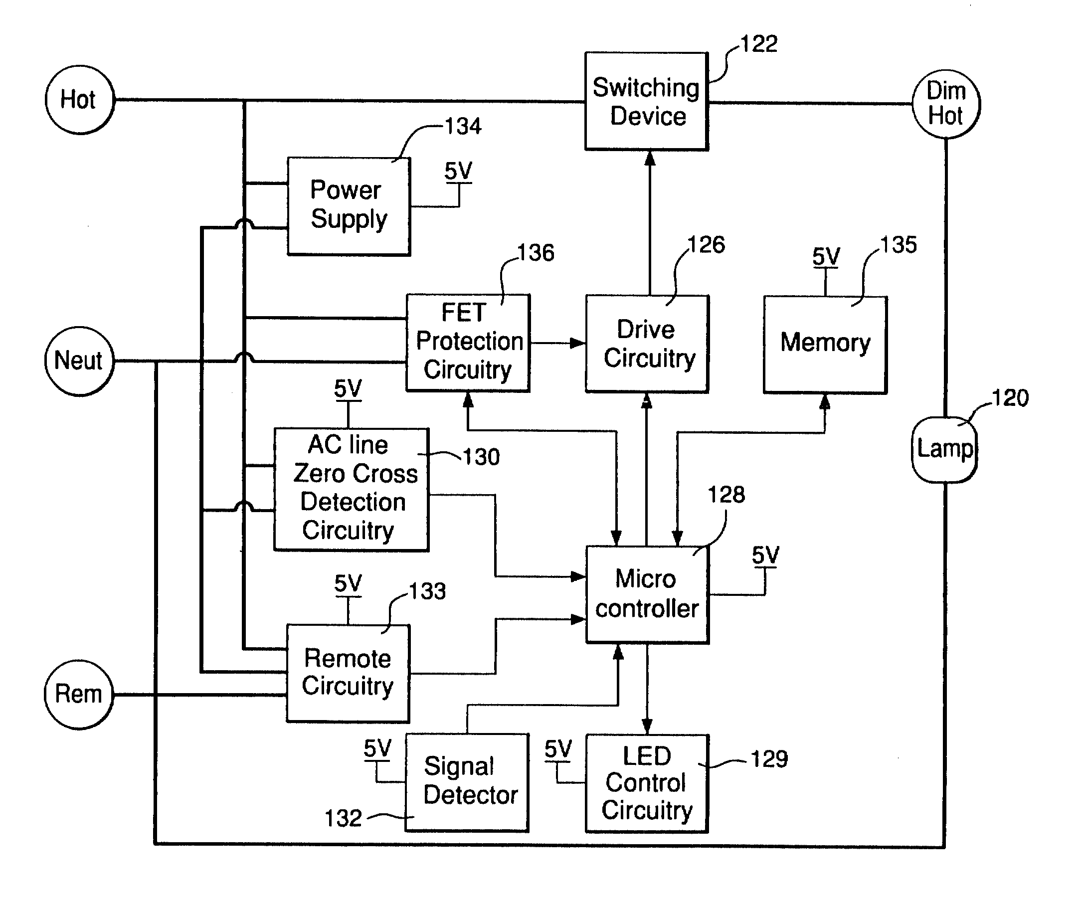
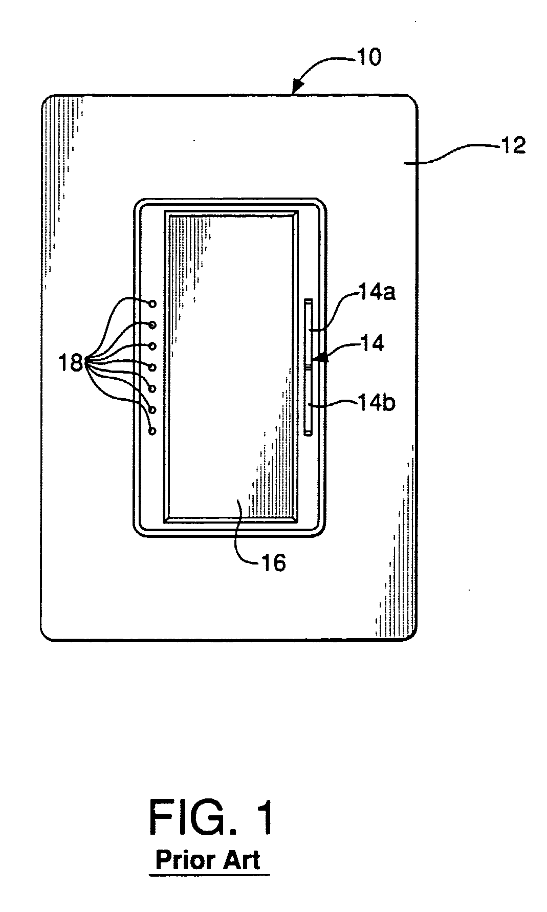
[0025]FIG. 3 depicts a wall control 100 embodying a lighting control device according to the invention. Wall control 100 comprises a bezel 102, intensity selection actuator 104 for selecting a desired level of light intensity of a lamp controlled by the device, and a control switch actuator 106. Bezel 102 need not be limited to any specific form, and is preferably of a type adapted to be mounted to a conventional wall box commonly used in the installation of lighting control devices. Actuators 104 and 106. likewise are not limited to any specific form, and may be of any suitable design which permits manual actuation by a user.

[0026] Actuator 104 may control a rocker switch, for example, but may also control two separate push switches, for example, without departing from the invention. The switches controlled by actuator 104 may be directly wired into the control circuitry to be described below, or may be linked by an extended wired link, infrared link, radio frequency link, power l...


PUM


Abstract

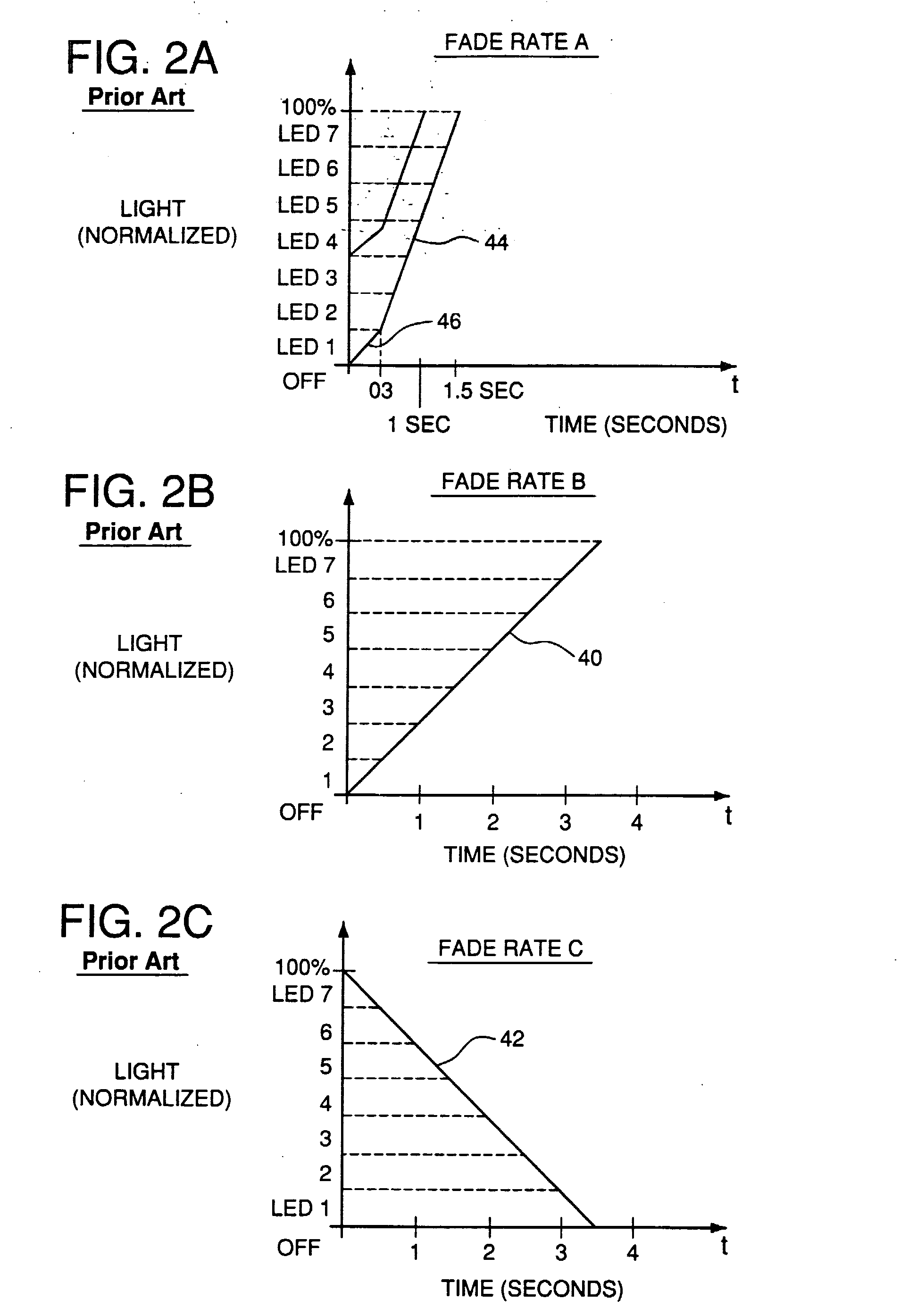
A lighting control device for controlling the light intensity level of at least one lamp is disclosed. The lighting control device includes an actuator and a controller, such as a microcontroller, for example. The controller is operable to cause the light intensity level of the lamp to fade at a first fade rate when the actuator is actuated. If the controller determines that the actuator has been actuated for at least a predefined hold time, the controller causes the light intensity level of the lamp to fade at a second fade rate for a predefined long fade time. After the long fade time elapses, the controller causes the light intensity level of the lamp to fade to off at a third fade. The first fade rate is based on a predefined fade-off time that represents a time allotted for fading the light intensity level of the lamp from its initial light intensity level to off. To prevent the light intensity level from fading to off before the hold time elapses, the fade off time may be defined to be longer than the hold time. The second fade rate may be slower than the first fade rate and have an exponential fade profile. The third fade rate may be a predefined rate at which the controller is operable to cause the light intensity level to fade from full on to full off. The third fade rate may be faster than the second fade rate.

Description

CROSS-REFERENCE TO RELATED APPLICATIONS [0001] This application is a continuation of U.S. patent application Ser. No. 10 / 753,035, filed Jan. 7, 2004. The contents of U.S. patent application Ser. No. 10 / 753,035 are incorporated herein by reference.FIELD OF THE INVENTION [0002] The invention relates generally to lighting control devices. More particularly, the invention relates to lighting control devices that employ a sequence of fade rates to fade the light intensity level of one or more lamps. BACKGROUND OF THE INVENTION [0003] Dimmer switches, i.e., wall-mounted light switches that include a dimmer, have become increasingly popular, especially for applications where it is desired to control precisely the level of light intensity in a particular room. Some known dimmer switches employ a variable resistor that is manipulated by hand to control the switching of a triac, which in turn varies the voltage input to the lamp(s) to be dimmed. Such manually-operated, variable resistor dimme...

Claims


Application Information

Patent Timeline
Patent Type & Authority Applications(United States)
IPC IPC(8): H05B37/02H05B39/08
CPCH05B39/083H05B39/086Y10S315/04H05B47/185
Inventor JOHNSON, BENJAMIN AARONKRUSE, GLEN ANDREWKEAGY, JON MICHAEL
Owner LUTRON TECH CO LLC
Learn More