Coplanar X-ray guided aiming arm for locking of intramedullary nails

a technology of aiming arm and nail, which is applied in the direction of bone drill guide, medical science, surgery, etc., can solve the problems of inability to achieve distal locking, inconvenient x-ray technician, and inability to perform distal locking satisfactorily, etc., and achieve the effect of helping the medical care area

Active Publication Date: 2006-05-18
SYNTHES USA
View PDF41 Cites 42 Cited by
  • Summary
  • Abstract
  • Description
  • Claims
  • Application Information

AI Technical Summary

Benefits of technology

[0019] It is therefore an object of the present invention to provide an aiming arm capable of being adjusted to compensate for the intramedullary nail distortion after its insertion into the bone, making use of the information given by a few snap shots of the X-ray image intensifier.
[0021] Further, it is an object of the present invention to reduce undesirable X-ray exposure to the surgeon, patient and operating room staff.
[0022] The present invention provides an easy and straightforward procedure for the X-ray technician and the surgeon and makes distal bone fixation of intramedullary nails simple and fast, thereby addressing one of the most important issues in actual surgery—time shortening.
[0023] The aiming arm of the present invention overcomes the disadvantages of conventional aiming arms by providing an easily obtainable X-ray guidance for distal locking without requiring that the X-ray beam be coaxial with the nail hole, thus reducing undesirable X-ray exposure to the surgeon, patient and operating room staff.
[0025] By fulfilling the objectives mentioned above, the present invention is extremely helpful to the medical care area.
[0026] The preferred embodiment of the present invention provides an adjustable aiming arm fastened to a bone nail. The aiming arm is constructed of a radiolucent material and has coplanar transverse holes or apertures. The aiming arm has a number of radiopaque target markers to enable the X-ray technician to assess when the position of an X-ray source is such that an X-ray beam is coplanar with the transverse holes of aiming arm. The image shown by a single X-ray snapshot in this position gives the surgeon precise information on the amount of nail distortion after nail insertion into the bone, thereby allowing the surgeon to determine the aiming arm adjustment needed to compensate for the distortion of the intramedullary nail. Once the aiming arm is accurately oriented over the nail hole, so that the aiming arm transverse holes are coaxial with the nail holes, the surrounding bone material can be drilled. After the bone is drilled, locking bone screws are screwed through the protective sleeves previously inserted into the aiming arm transverse holes.

Problems solved by technology

However, distal screw holes may not perform satisfactorily due to distortion of the intramedullary nail while being driven into the bone and / or mechanical stress on the aiming arm.
However, it is usually not successful for distal locking except for very short nails since the distortion of the nail when inserted into the bone is not negligible.
However, flexion distortion in a plane perpendicular to the plane of the distal screw holes of the nail is very important and the distortion of concern when distal locking is the objective.
The procedure starts by exactly positioning the X-ray beam in the axis of the nail holes, something that is not always straightforward for the X-ray technician.
In particular, the nail hole will appear as a circle when the X-ray source is positioned such that the X-ray beam is parallel to the axis of the nail hole, something that is a complex 3D procedure.
This is not always simple, and sometimes not even possible.
It may also increase undesirable X-ray exposure to the surgeon, patient and operating room staff, and lengthen the surgical procedure.
However, most of these systems are cumbersome and require additional bone screw holes in order to exactly assess the position of the hole in the distorted intramedullary nail after implantation into the bone.

Method used


Image

  • Coplanar X-ray guided aiming arm for locking of intramedullary nails
  • Coplanar X-ray guided aiming arm for locking of intramedullary nails
  • Coplanar X-ray guided aiming arm for locking of intramedullary nails

Examples


Embodiment Construction

[0049] Hereinafter, a method of bone fixation according to the preferred embodiment of the present invention will be explained with reference to FIGS. 1-7.

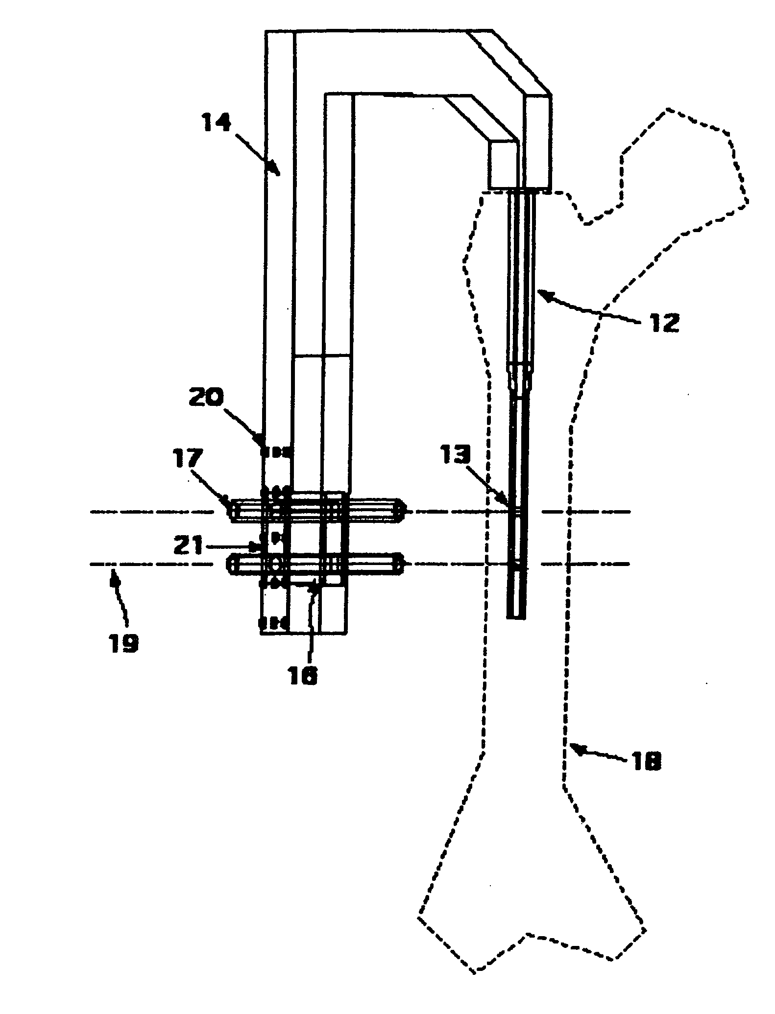
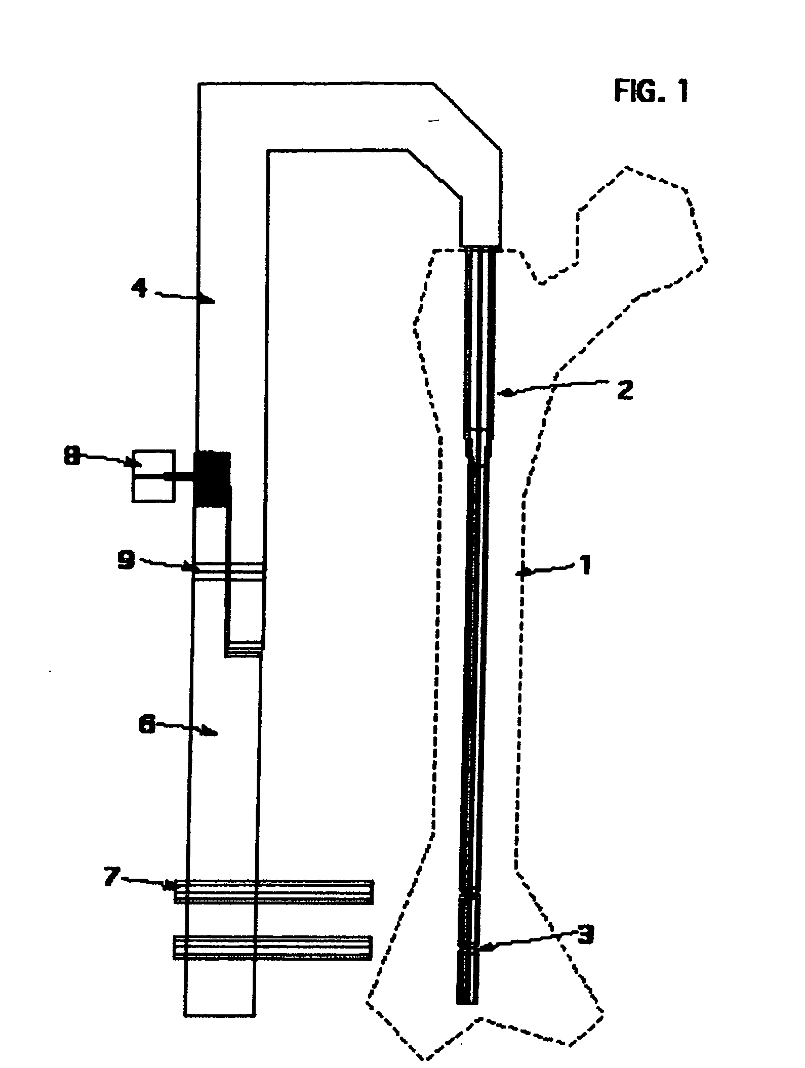
[0050] Referring to FIG. 1 there is shown an aiming device 4, on which is mounted a mobile aiming arm portion 6. An intramedullary nail 2, with two coplanar transverse holes 3 is fastened to the aiming arm 4. Protective sleeves 7 slide through holes 5 located in the mobile part of the aiming arm 6, guiding drills and bone screws through the nail transverse holes 3 for distal locking of the intramedullary nail 2. Mobile aiming arm portion 6 rotates about the axis 9 with respect to aiming arm 4.

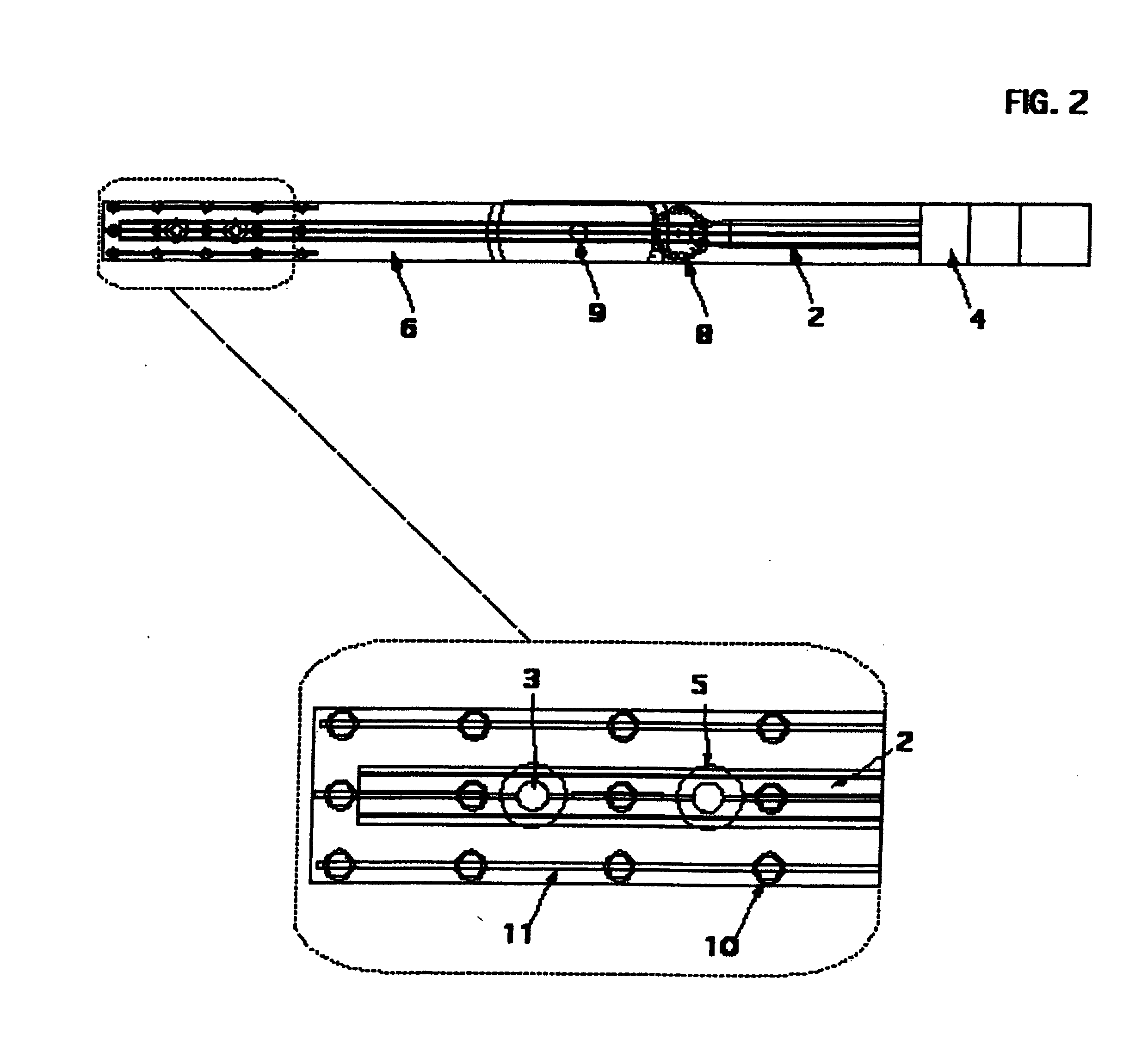
[0051] The aiming arm 4 is fastened to the intramedullary nail 2, and before the nail 2 is inserted into the bone 1, aiming arm holes 5 and intramedullary nail holes 3 are precisely aligned as shown in FIGS. 2 and 3.

[0052] After implantation into the bone, the distortion of the intramedullary nail causes the intramedullary nail holes 3 to ...


PUM


Abstract

A novel coplanar X-ray guided method and device for insertion of distal locking screws in intramedullary bone nails. The device has coplanar holes, which allow insertion of protective sleeves. A drill and bone screws can be inserted through the protective sleeves. Radiopaque target markers in the aiming arm enable the easy positioning of an X-ray source such that an X-ray beam is coplanar with the aiming arm transverse holes. After the X-ray source is accurately oriented, a single X-ray snapshot is enough to assess the exact distortion of the implanted intramedullary nail. The X-ray beam need not be coaxial with the intramedullary nail holes. The aiming arm has a mobile portion and a fixed portion fastened to the nail, wherein said aiming arm can be adjusted, displacing the mobile portion over the fixed portion, to compensate for the distortion of the intramedullary nail after implantation. Once the aiming arm is precisely positioned, the aiming arm transverse holes and intramedullary nail holes are accurately aligned, protective sleeves are inserted through aiming arm holes, bone drills are drilled through the intramedullary nail holes and surrounding bone material, and bone screws are inserted, locking the intramedullary nail to the bone.

Description

RELATED APPLICATION DATA [0001] The present application is a continuation-in-part of co-pending U.S. patent application Ser. No. 10 / 947,155, filed Sep. 23, 2004.FIELD OF INVENTION [0002] The present invention is directed to aiming arm locking of intramedullary nails, and in particular to X-ray guided aiming arm locking of intramedullary nails. BACKGROUND OF THE INVENTION [0003] It is well known the use of intramedullary nails to treat bone fractures in tubular bones. A nail is implanted in the medullary canal of the bone across the fracture site in order to retain the bone fragments on the bone nail and to secure the bone fragments from being displaced. The nail has transverse holes and is fixed to the bone by a number of locking screws or fixation bolts which must pass through holes in the nail and into the surrounding bone material. After the nail is inserted into the medullary canal, the distal end of the nail is invisible to the naked eye. Numerous methods and apparatus have bee...

Claims


Application Information

Patent Timeline
Patent Type & Authority Applications(United States)
IPC IPC(8): A61B17/58
CPCA61B17/1703A61B17/1725A61B19/54A61B2017/00831A61B2017/00915A61B90/39A61B17/17A61B17/56A61B17/58A61B17/60
Inventor FERNANDEZ, ALBERTOBUTTLER, MARKUSWAELCHLI, ANDREAS
Owner SYNTHES USA
Why Eureka
Try Eureka