Aiming Arm for Locking of Bone Nails

a technology for locking bones and nails, applied in bone drill guides, medical science, surgery, etc., can solve the problems of difficult x-ray technicians, difficult to accurately align the distal screw holes, and sometimes not even possible, so as to facilitate the targeting and installation of screws, accurately and reliably

Inactive Publication Date: 2011-07-28
DEPUY SYNTHES PROD INC
View PDF8 Cites 13 Cited by
  • Summary
  • Abstract
  • Description
  • Claims
  • Application Information

AI Technical Summary

Benefits of technology

[0008]The present invention relates to a novel apparatus and method for locking intramedullary...

Problems solved by technology

However, even when the aiming arm ensures accurate insertion of the proximal end of the nail, distal screw holes may not be properly aligned if the nail is deformed while being driven into the bone.
However, this may be difficult for the X-ray technicia...

Method used


Image

  • Aiming Arm for Locking of Bone Nails
  • Aiming Arm for Locking of Bone Nails
  • Aiming Arm for Locking of Bone Nails

Examples


Embodiment Construction

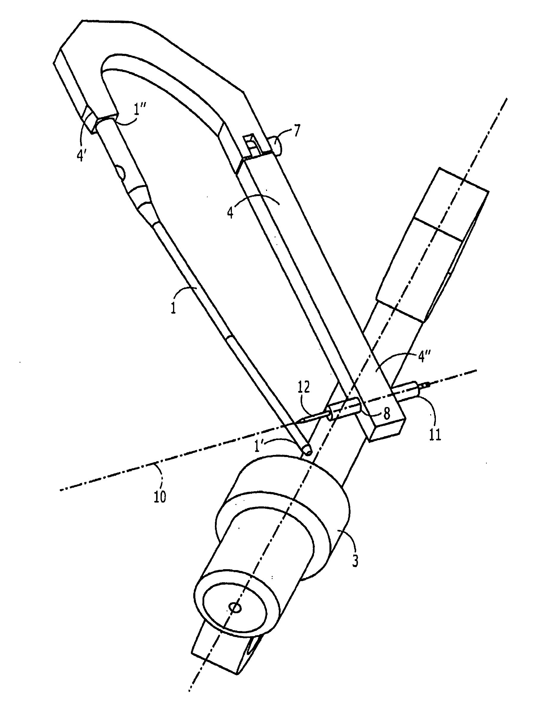
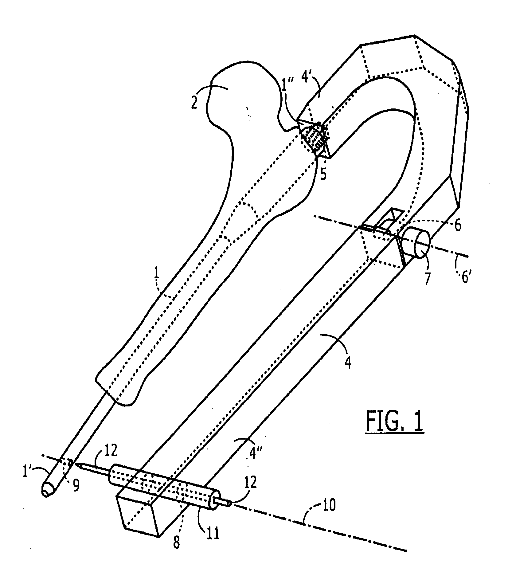
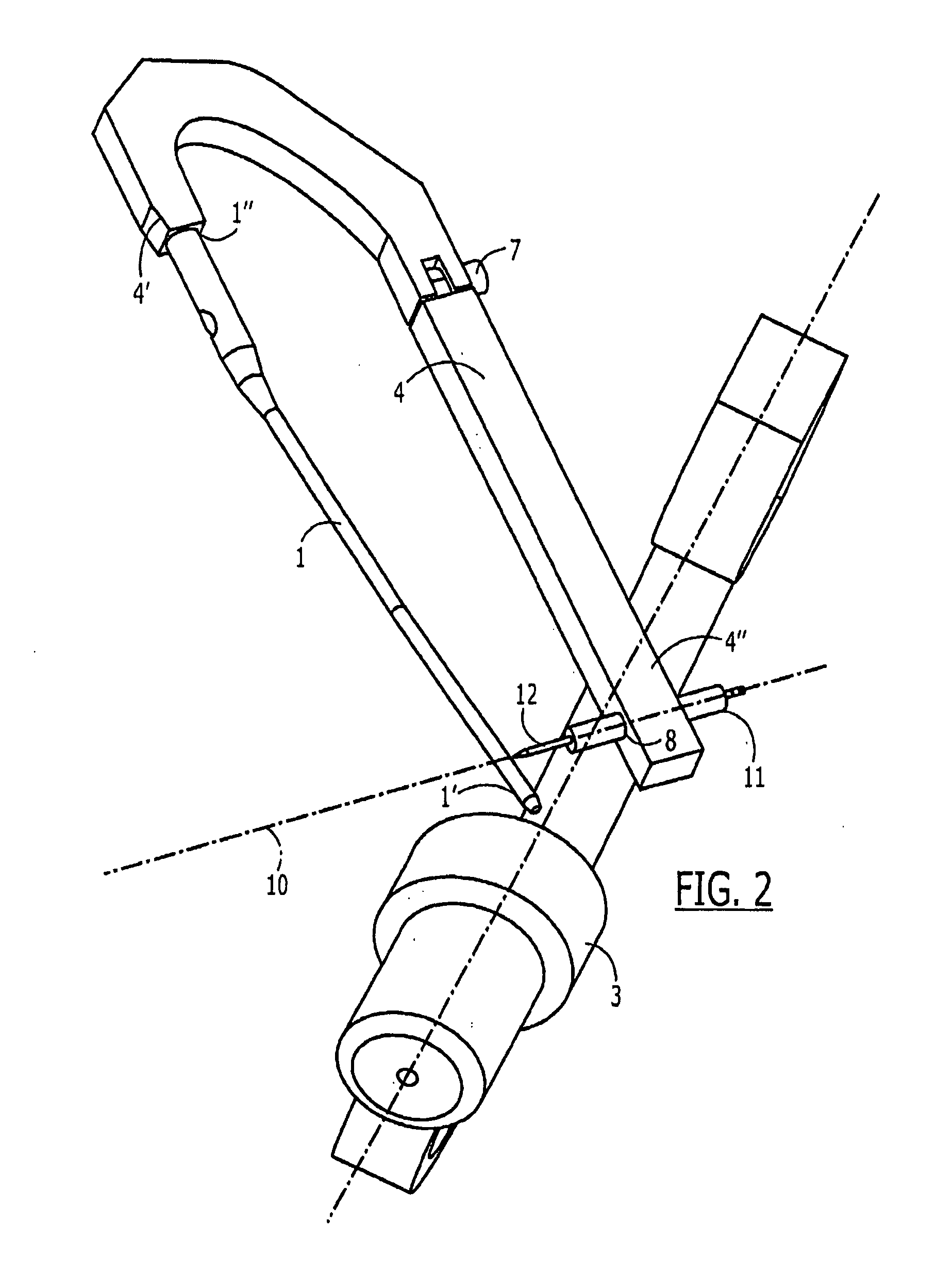
[0025]The present invention may be further understood with reference to the following description and the appended drawings, wherein like elements are referred to with the same reference numerals. The present invention relates generally to methods and devices for the stabilization and fixation of fractured bones and bone fragments. Specifically, the present invention relates to methods and devices for the stabilization and / or fixation of long bones through the insertion of a stabilizing member longitudinally thereinto. For example, the present invention relates to the placement and fixation of an intramedullary nail within the medullary canal of a long bone such as the femur, humerus, tibia, etc. However, those skilled in the art will understand that the present invention may be employed in stabilizing any long bone through the insertion into a medullary canal thereof of an intramedullary member. Thus, the discussion of this invention in regard to the stabilization of a femur with a...


PUM


Abstract

An aiming arm (4) comprises a rigid distal member a distal portion (4′) of which is configured to be releasably coupled to a proximal end (1″) of an implant (1) to be implanted in a medullary canal of a bone (2), so that, when coupled to the proximal end of an implant, an orientation of the proximal end of the implant relative to the distal portion of the aiming arm remains constant in combination with a rigid proximal member (4″) a distal portion of which is rotatably coupled to a proximal end of the distal member. The proximal member includes an aligning feature (8) defining an axis. (10) aligned with an axis of a fixation element receiving hole (9) extending through a distal portion of the implant, the proximal member being rotatable after implantation of the implant, to an adjusted configuration in which the aligning feature is aligned with a post-implantation orientation of the fixation element.

Description

BACKGROUND INFORMATION[0001]Bone nails such as intramedullary nails are usually locked at two locations—at a first location close to the entry point and a second location far from the entry point. The end of the nail which is inserted into the bone and penetrates most deeply from the entry site is identified as the distal end while the end of the nail that remains adjacent to the entry site is referred to as the proximal end. As used in this application, the term distal refers to a direction away from an insertion point of an intramedullary implant (i.e., the leading end which is first inserted into the bone is the distal end regardless of the end of the bone into which this leading end is inserted) while the term proximal refers to the opposite direction. The locking of such nails is currently done using either mechanical aiming instruments (e.g., aiming arms) or X-ray guidance.[0002]Mechanical aiming instruments such as those disclosed in U.S. Pat. No. 6,514,253 are generally remo...

Claims


Application Information

Patent Timeline
IPC IPC(8): A61B17/56
CPCA61B17/1703A61B2017/1778A61B17/72A61B17/1725A61B17/1778
Inventor DELL'OCA, ALBERTO A. FERNANDEZBUETTLER, MARKUS
Owner DEPUY SYNTHES PROD INC
Why Eureka
Try Eureka