Retaining wall block with face connection

a technology of face connection and retaining wall, which is applied in the field of retaining wall blocks, can solve the problems of visible line or seam between, disadvantages of prior art continuous front flanged blocks, and difficulty in forming smooth inside or outside curves in walls formed from blocks

Inactive Publication Date: 2006-05-25
CONTECH TECH
View PDF41 Cites 173 Cited by
  • Summary
  • Abstract
  • Description
  • Claims
  • Application Information

AI Technical Summary

Benefits of technology

[0010] The invention comprises first and second wall block systems which include face connection systems which allow for construction of a wall providing safety and stability as well as a desired face appearance.

Problems solved by technology

One disadvantage of using blocks having a rear flange is that their use naturally creates a setback between courses which produces a visible line or seam between courses which is noticeable to an observer.
As with rear flanged blocks, there are disadvantages of prior art continuous front flanged blocks.
First, their use naturally creates a set back that accentuates the horizontal lines between succeeding courses of the retaining wall.
Second, the continuous flange on these blocks makes it difficult to form smooth inside or outside curves in a wall formed from the blocks.
Third, because the flange of a front (or rear) flanged block extends in a straight line across the entire width of the block, the blocks tend to set back excessively when a curve in the wall is constructed.

Method used


Image

  • Retaining wall block with face connection
  • Retaining wall block with face connection
  • Retaining wall block with face connection

Examples


first embodiment

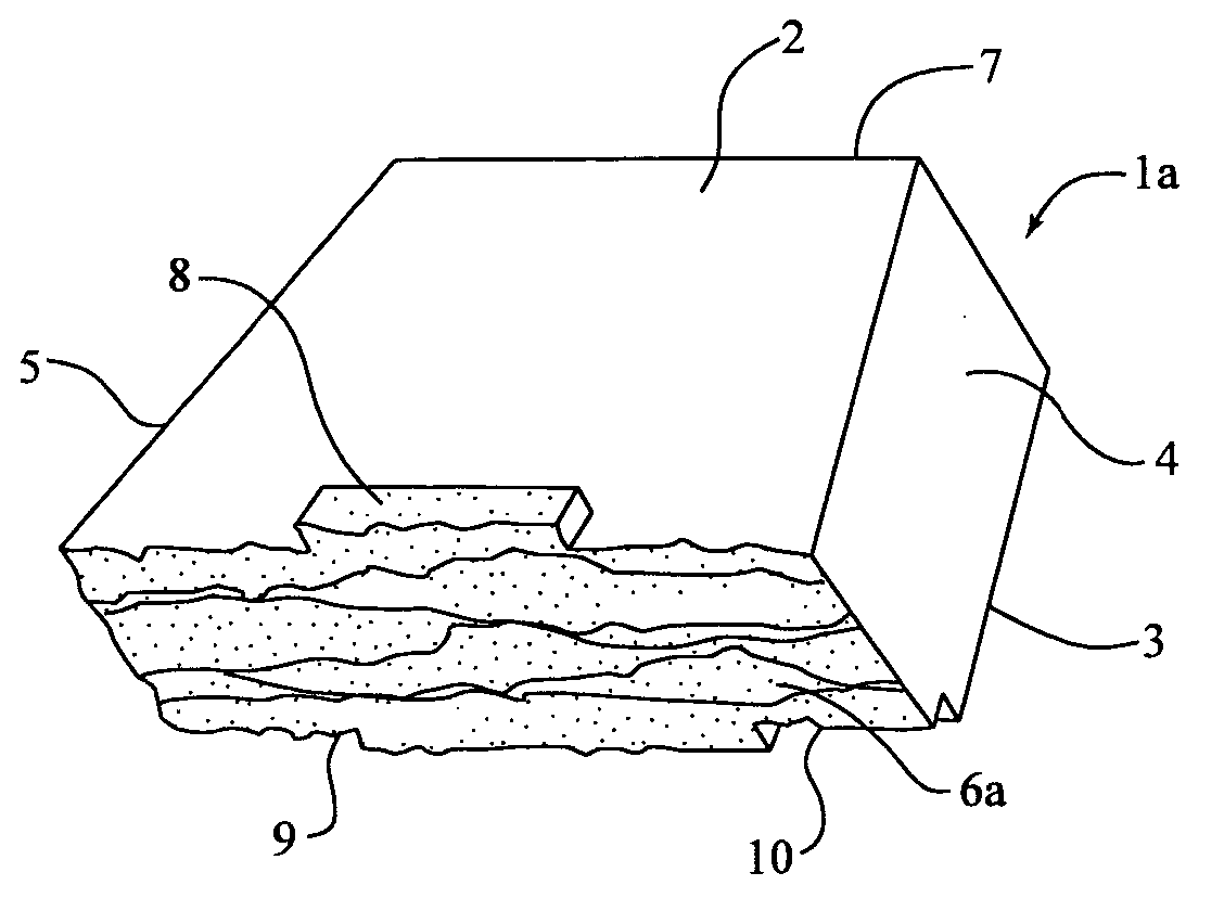
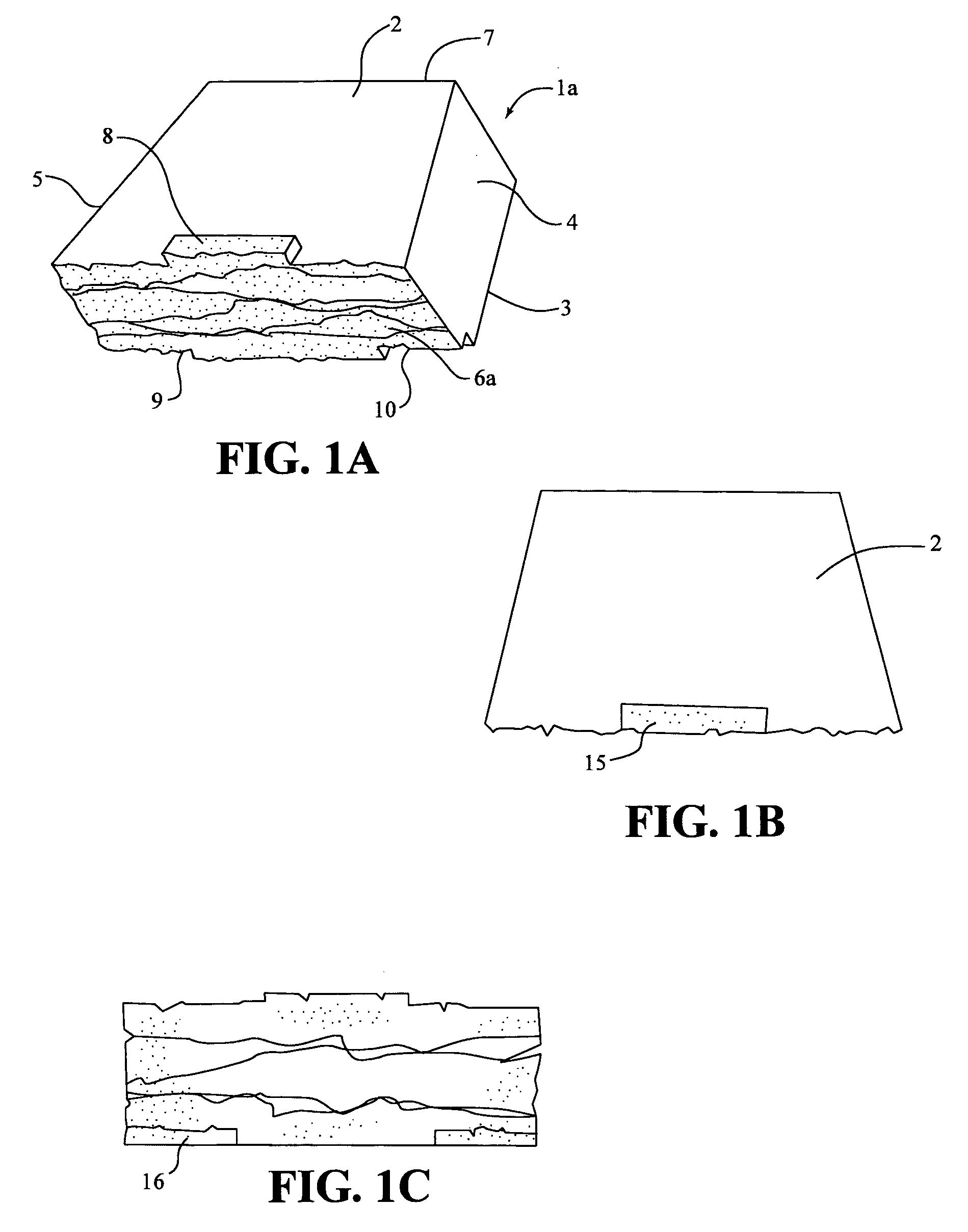
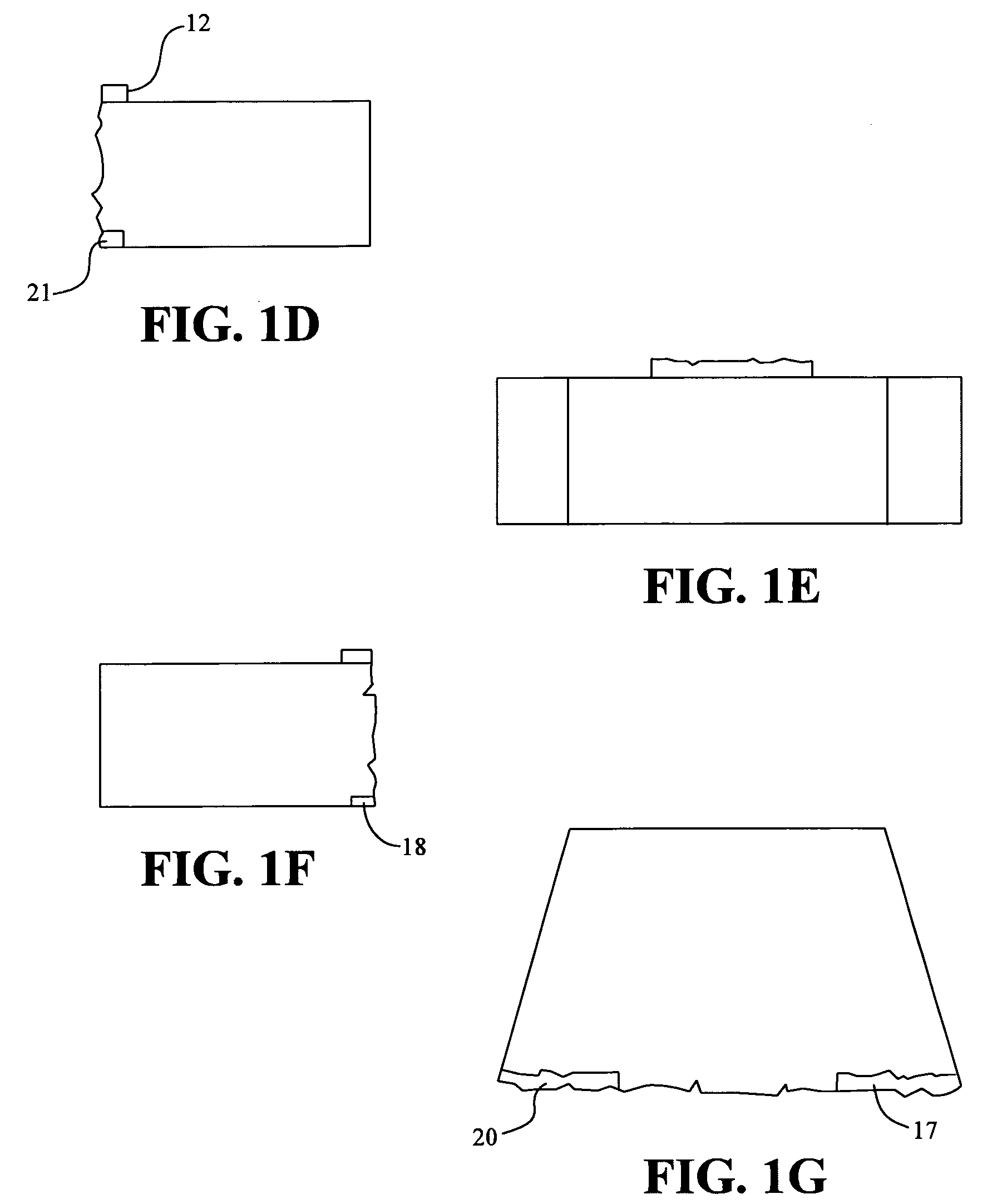
[0042] The single block wall system is shown in FIGS. 1 to 5. the block is shown in FIGS. 1A to 1G which illustrate perspective, top, front, right side, back, left side and bottom views, respectively, of block 1a. Block la has a top surface 2 which is substantially parallel to a bottom surface 3, nonparallel first and second side wall surfaces 4 and 5, and a front face 6a which is substantially parallel to a rear surface 7.

[0043] The front face 6a and rear surface 7 each extend from top surface 2 to bottom surface 3. First and second side surfaces 4 and 5 extend from top surface 2 to bottom surface 3 and from front face 6a to rear surface 7. The top and bottom surfaces, side surfaces, front face and rear surface collectively define a block body. The size of the bocks may be similar to presently used retaining wall blocks. By way of non limiting example the blocks may be between 12-18 inches wide, 7-12 inches deep and 3-8 inches in height. Block 1a is generally symmetrical about a ve...

second embodiment

[0052] the single block system is shown in FIGS. 4 and 5. Block 1b is similar in all respects to block 1a except that the front face 6b is provided with an ashlar surface pattern instead of the ledgestone pattern of front face 6a. The description of the various features of block 1a and the construction of a retaining wall therefrom are applicable with respect to block 1b and will not be repeated. The only significant difference between blocks 1a and 1b is the front face contour and the appearance which is created when the blocks are used to construct a retaining wall.

[0053] A retaining wall constructed with blocks 1b is shown in FIG. 5. In accordance with the discussion regarding the manufacture of block 1a with up to four different surface configurations FIG. 5, for purposes of illustration, shows a partial retaining wall constructed from blocks 1b showing only the surface configurations of four potential surface contours of block 1b. Construction of the wall in its intended manner...


PUM


Abstract

Single and multiple retaining wall blocks and block systems are disclosed. The blocks are provided with a face connection system which includes at least one front lip extending from a top surface of the block and a bottom channel formed into a front face and bottom surface of the block. The front lips have a length which is less than the width of the blocks.

Description

[0001] This application claims the benefit of U.S. Provisional Patent Application No. 60 / 630,898, filed Nov. 24, 2004, the contents of which are hereby incorporated herein by reference.FIELD OF THE INVENTION [0002] The present invention relates to retaining wall blocks having a front face connection system and to retaining walls constructed from those blocks and to methods of making the blocks and constructing walls from the blocks. BACKGROUND OF THE INVENTION [0003] Numerous methods and materials exist for the construction of retaining walls. Such methods include the use of natural stone, pored in place concrete, masonry, and landscape timbers or railroad ties. In recent years, segmental concrete retaining wall units which are dry stacked (i.e., built without the use of mortar, have become a widely accepted product for the construction of retaining walls. Such products have gained popularity because they are mass produced, and thus relatively inexpensive. They are structurally soun...

Claims


Application Information

Patent Timeline
Patent Type & Authority Applications(United States)
IPC IPC(8): E02D17/00E04C2/04
CPCB28B3/021B28B7/0097B28B7/24E02D29/025E04B2002/0206E04B2002/0269E04C1/395E02D17/00E02D29/02E04C1/00
Inventor DAWSON, WILLIAM B.MACDONALD, ROBERT A.
Owner CONTECH TECH
Why Eureka
Try Eureka