Flying toy

a flying toy and toy technology, applied in the field of flying toy, can solve the problems of impairing external appearance, unable to play with the character doll by causing it to freely ascend/descend or hover in the air, etc., and achieve the effect of stabilizing a postur

Inactive Publication Date: 2006-06-08
TAIYO KOGYO CORPORATION
View PDF5 Cites 45 Cited by
  • Summary
  • Abstract
  • Description
  • Claims
  • Application Information

AI Technical Summary

Benefits of technology

[0008] In the invention according to claim 2, the stabilizer and the upper rotor are attached so that surfaces of rotor blades of the upper rotor tilt in conjunction with the stabilizer via a link when the stabilizer tilts from a horizontal position. The stabilizer and the upper rotor are actuated in conjunction with each other, thereby making it possible to easily stabilize the posture.

Problems solved by technology

Moreover, when the character doll is suspended by the line from a ceiling or the like to cause it to fly, the character doll only circles around a point at which it is suspended from the ceiling or the like, and it is thus impossible to play with the character doll by causing it to freely ascend / descend or to hover in the air to a certain degree.
On the contrary, for example, when a single-rotor type helicopter device is incorporated into the character doll, it is necessary to attach a tail rotor to the character doll, which might impair external appearance.

Method used


Image

  • Flying toy
  • Flying toy
  • Flying toy

Examples


first embodiment

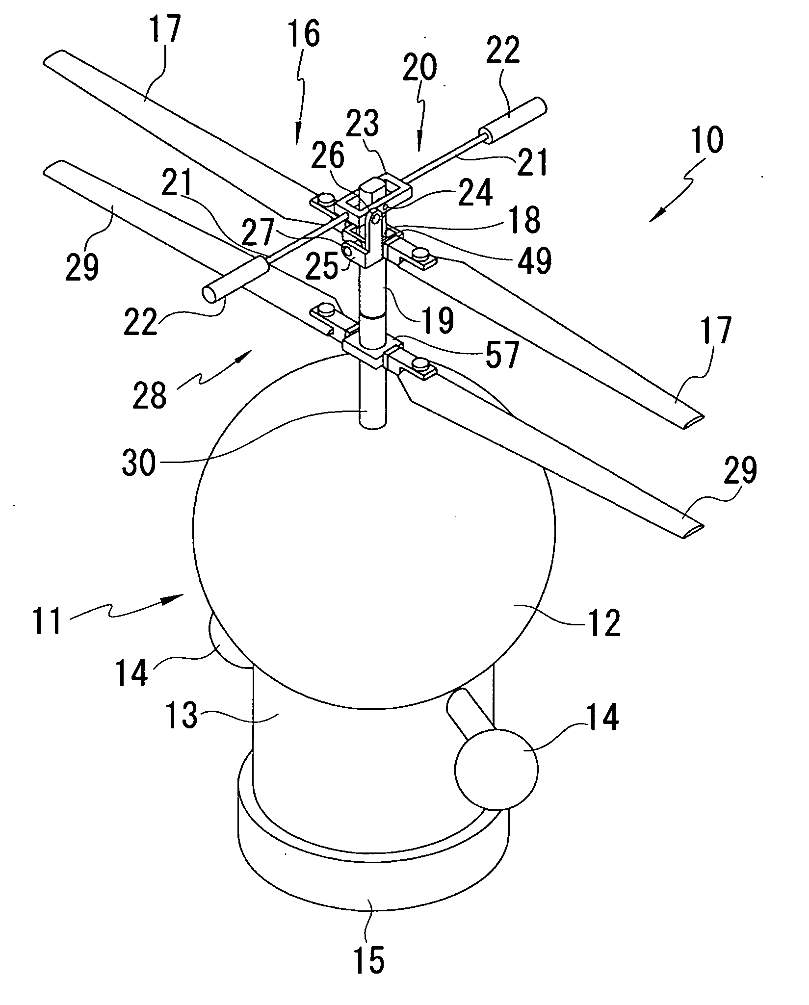
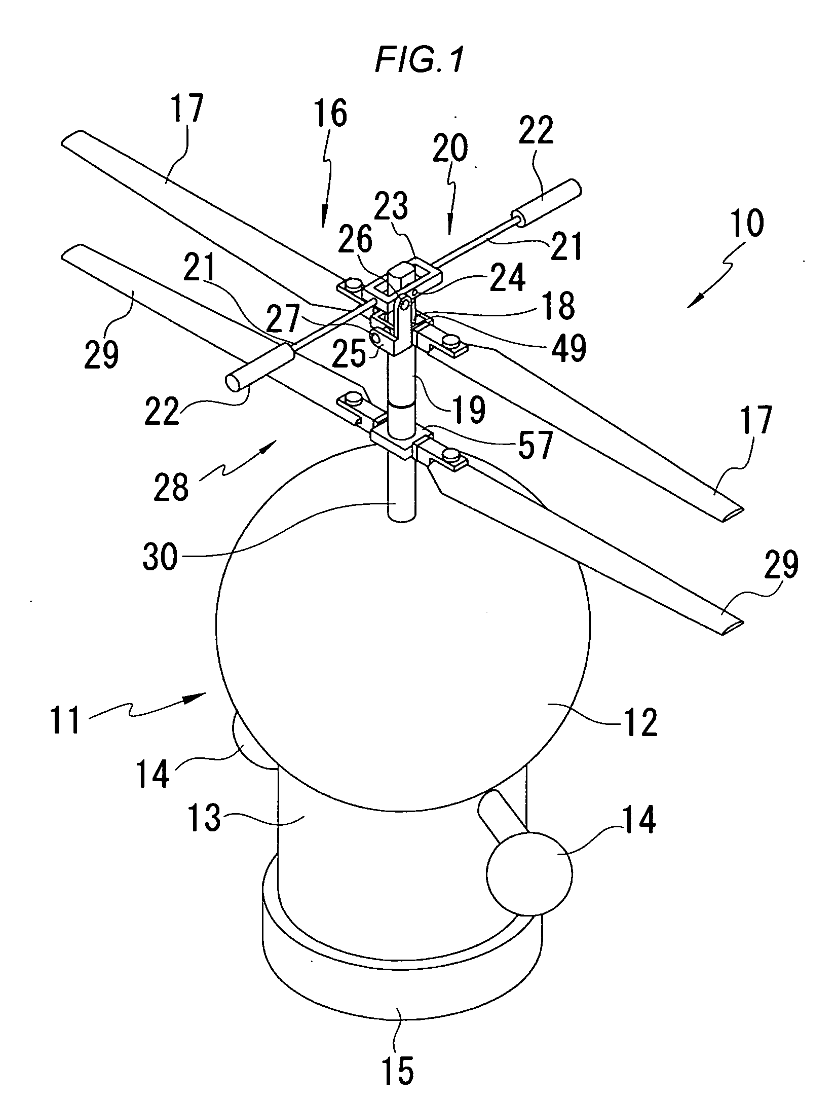
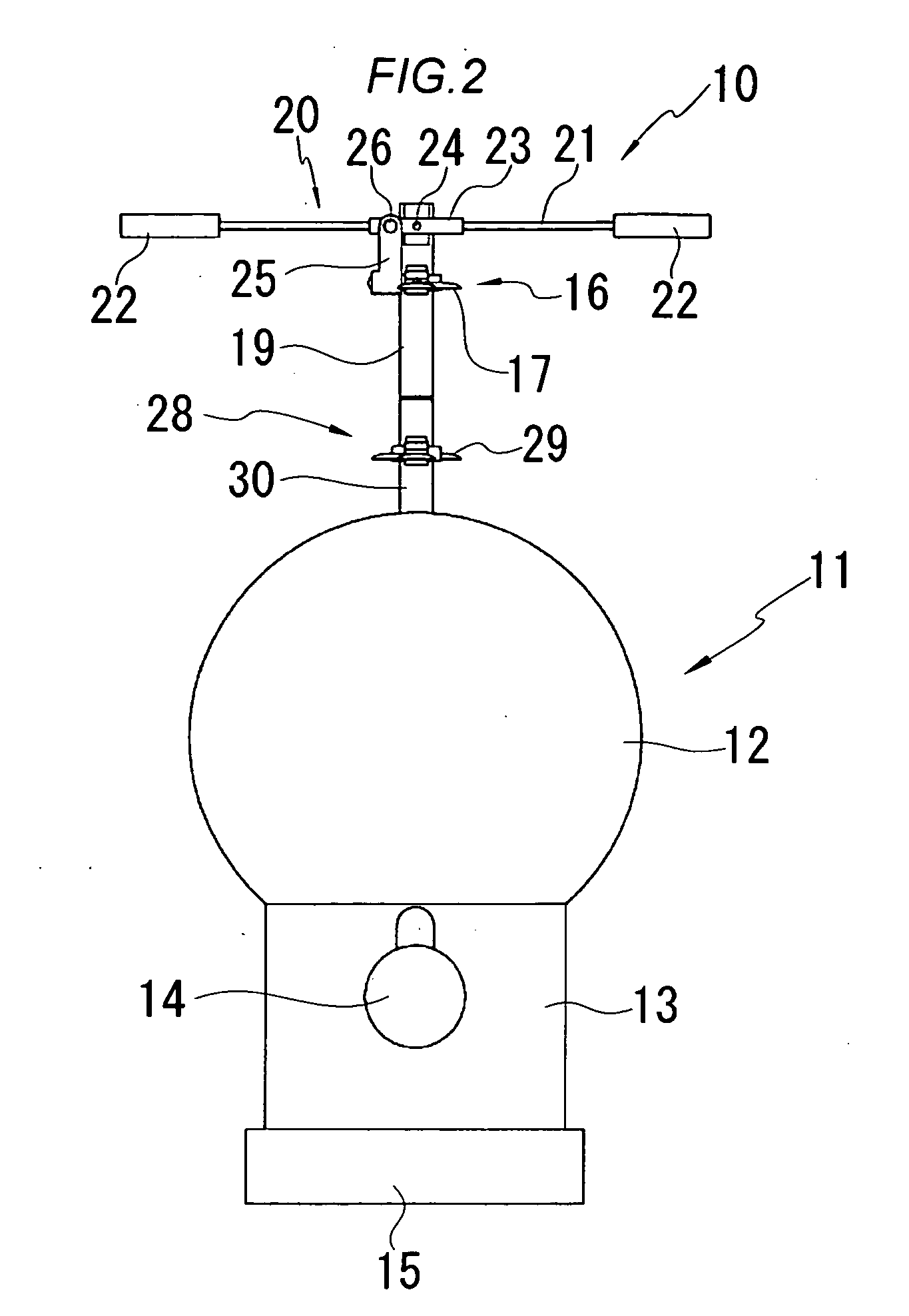
[0021] The present invention will hereinafter be specifically described with reference to one embodiment shown in the drawings. FIGS. 1 to 9 are diagrams to explain a flying toy in the present invention. FIG. 1 is a perspective view of the flying toy; FIG. 2 is a side view of the flying toy; FIG. 3 is a sectional view of a flying object part of the flying toy; FIG. 4 is an enlarged sectional view showing a driver of the flying object; FIG. 5 is a view in an arrow A direction of a gear portion in FIG. 4; FIGS. 6 to 8 are diagrams to explain an operation of a rotor portion; and FIG. 9 is a block diagram to explain a control operation of the flying toy.

[0022] A flying toy 10 of the present embodiment comprises: a flying object 11 which replicates a model such as a doll having an optional character; an upper rotor 16 and a lower rotor 28 which are provided on the top of the flying object 11 and which concentrically rotate in directions opposite from each other; a stabilizer 20 which rot...

second embodiment

[0034] In the flying toy 50 of the second embodiment, since the upper rotor 16, the lower rotor 28 and the stabilizer 20 are provided on the top of the rear side part 56 of the flying object 51, it is possible to play with the flying toy by causing it to freely ascend / descend or to hover in the air to a certain degree without rotating the flying object 51 itself, and the horizontal posture can be maintained to achieve a stable operation, and moreover, the flying object 51 having a character such as a doll can be caused to look as if it is carrying luggage or the like on its back.

[0035] It is to be noted that in the embodiments described above, the flying object 11, 51 may be in any form as long as it is modeled on a character doll having an optional shape or the like, and it is not limited to the shape and the like of the embodiments. Further, the stabilizer 20 may be in any form as long as it rotates in conjunction with at least one of the rotors which rotate opposite from each oth...


PUM


Abstract

A flying toy is provided in which a flying object on a model having an optional character can be caused to freely ascend / descend or hover by remote control. The flying toy comprises: a flying object which replicates a model having a character; and upper rotor and a lower rotor which are provided on the top of the flying object and which concentrically rotate in directions opposite from each other; a stabilizer which rotates in conjunction with at least one of the rotors and which stabilizes a posture; a driver which is provided inside the flying object and which rotates the upper rotor, the lower rotor and the stabilizer; a control circuit for remote control to control an operation of the driver and a battery to serve as a power source which are provided inside the flying object.

Description

BACKGROUND OF THE INVENTION [0001] 1. Field of the Invention [0002] The present invention relates to a flying toy in which a flying object on a model having an optional character can be caused to freely ascend / descend and hover by remote control. [0003] 2. Description of the Related Art [0004] There has heretofore been proposed a toy to play by flying a model such as a doll having an optional character in the air. For example, a flying toy has been proposed wherein a wing is attached to an upper part of a flying object comprising a character doll, turning force is manually applied to the flying object by a propeller, and the flying object is caused to ascend and fly by lift force produced in the wing using a principle of Taketonbo or a T-shaped flying toy made of bamboo (refer to Japanese Registered Utility Model Publication No. 3024905 (page 2, FIG. 1)). There has also been proposed a character flying toy wherein a propulsion shaft provided with a propeller projects from a characte...

Claims


Application Information

Patent Timeline
Patent Type & Authority Applications(United States)
IPC IPC(8): A63H27/127
CPCA63H27/12
Inventor ISAWA, KUNIKAZU
Owner TAIYO KOGYO CORPORATION
Why Eureka
Try Eureka