Work machine safety device

a safety device and working machine technology, applied in the direction of electric/magnetic computing, analogue processes for specific applications, instruments, etc., can solve the problems of working machine balance loss and tipping, and achieve the effect of recognizing current stability quickly and precisely

Active Publication Date: 2014-07-01
NIHON KENKI CO LTD
View PDF10 Cites 17 Cited by
  • Summary
  • Abstract
  • Description
  • Claims
  • Application Information

AI Technical Summary

Benefits of technology

[0013]The present invention is equipped with the above-described configuration, and therefore, can provide a safety system for a working machine, which allows an operator to instantaneously, readily and precisely recognize current stability during work including operations of a front working mechanism and swing operations.

Problems solved by technology

The working machine may, therefore, lose a balance and tip over if an unreasonably aggressive operation is performed.

Method used


Image

  • Work machine safety device
  • Work machine safety device
  • Work machine safety device

Examples


first embodiment

[0032]With reference to the drawings, a description will hereinafter be made about the first embodiment of the present invention.

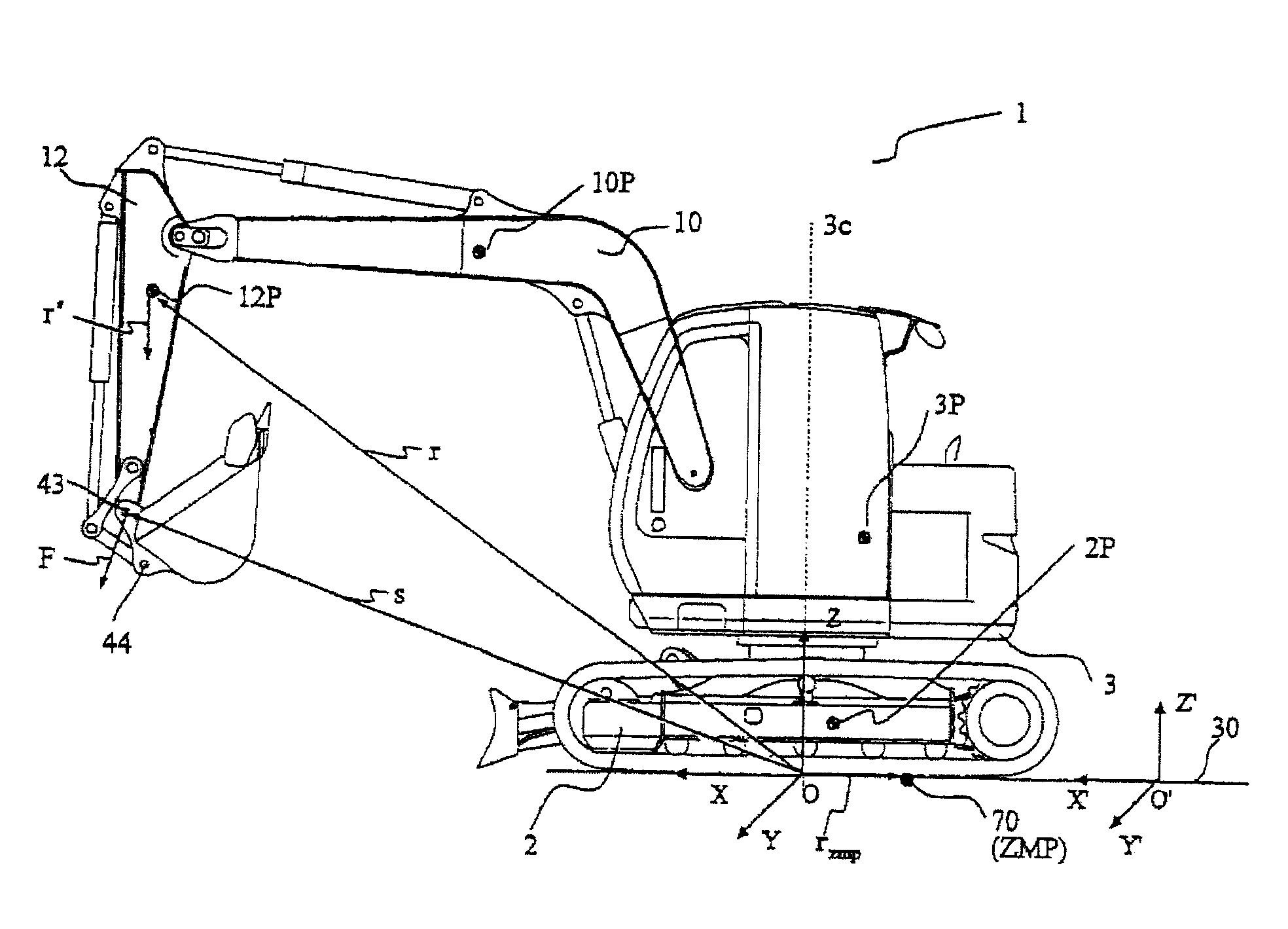
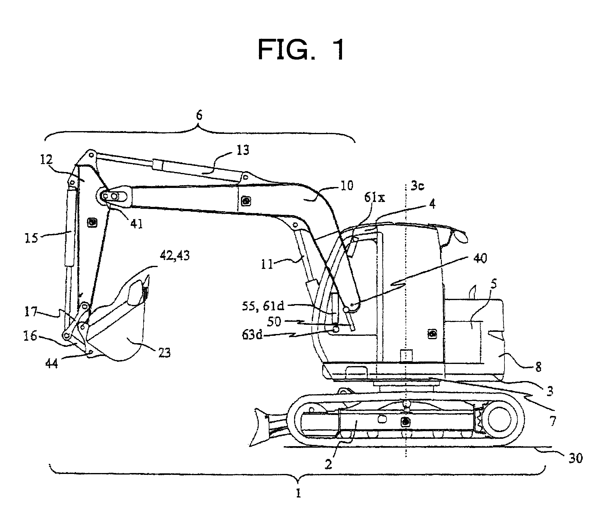
[0033]FIG. 1 is a side view of a working machine to which the present invention is applied. In the working machine 1, an upperstructure 3 is rotatably mounted on an upper section of an undercarriage 2, and the upperstructure 3 is rotatably driven about a center line 3c by a swing motor 7. On the upperstructure 3, an operator's cab 4 and an engine 5 which makes up a power system are mounted. On a rear part of the upperstructure 3, a counterweight 8 is mounted. Numeral 30 designates a ground surface. The upperstructure 3 is further provided with an operation control system that controls start and stop and entire operations of the working machine 1.

[0034]In a front working mechanism 6 arranged on a front of the working machine 1, a boom cylinder 11 is a drive actuator for pivoting a boom 10 about a fulcrum 40, and is connected to the upperstructure 3 and boom...

second embodiment

[0131]The second embodiment of the present invention will next be described. In the second embodiment, a barycentric position, which is a mass center of the working machine 1, is used instead of the ZMP in the first embodiment. With reference to FIG. 12, a description will hereinafter be made primarily about this difference from the first embodiment.

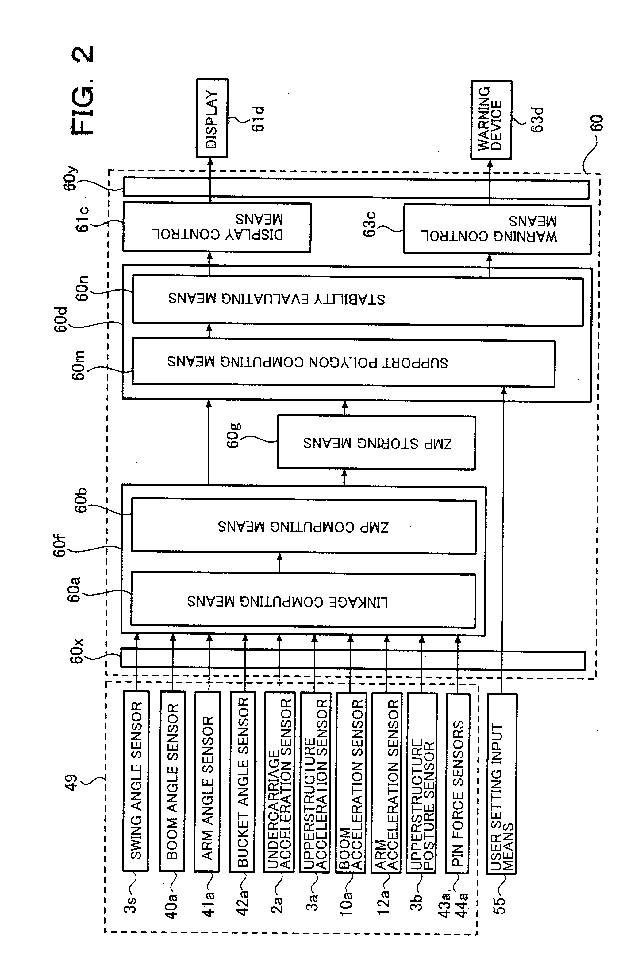
[0132]A state quantity sensing means 49 in the second embodiment is provided with the posture sensor 3b, boom angle sensor 40a, arm angle sensor 41a, bucket angle sensor 42a and pin force sensors 43a,44a out of the sensors in the first embodiment.

[0133]A linkage computation is performed as in the first embodiment. In the second embodiment, detection values of the posture sensor 3b, swing angle sensor 3s, boom angle sensor 40a and pin force sensors 43a, 44a are sent to the linkage computing means 60a. The position vectors r2,r3,r10,r12 at the respective mass points 2P, 3P, 10P, 12P, the position vectors s43, s44 of the pins 43,44 and the ...

third embodiment

[0148]The third embodiment of the present invention will next be described with reference to FIG. 13 to FIG. 14. Different from the first and second embodiments, the third embodiment performs prediction of a behavior of the ZMP position 70 in the near future, and performs a display and warning by using predicted values. As a consequence, a still more prompt and flexible response is feasible. A description will hereinafter be made primarily about this difference from the second embodiment.

[0149]At a ZMP predicting means 60c, a predicted value 71 of a ZMP position in the near future is calculated. Taking as an example a case in which the mass center 70b is used as the ZMP position 70, a description will be made about a method that calculates the predicted ZMP position 71 by using the current ZMP position 70 and ZMP position record 72.

[0150]When discussing changes in the ZMP position over a very short time, the moving speed of the ZMP position can be considered to be substantially cons...


PUM


Abstract

Disclosed is a safety system for a working machine, which allows an operator to instantaneously, readily and precisely recognize current stability during work including operations of a front working mechanism and swing operations. In a safety system for a working machine, a controller is provided with a ZMP calculating means (60f) for calculating coordinates of a ZMP by using position information, acceleration information and external force information on respective movable portions of a main body, which includes a front working mechanism, and undercarriage, and a stability computing means (60d) for calculating a support polygon formed by plural ground contact points of the working machine with a ground, and, when the ZMP is included in a warning region formed inside a perimeter of the support polygon, producing a tipping warning; the safety system is provided with a display (61d) for displaying a top plan view of the working machine and a ZMP position of the working machine relative to the support polygon; the ZMP calculating means and stability computing means compute and display the ZMP position and the support polygon including the warning region therein; and the safety system produces a tipping warning when the calculated ZMP position is included in the warning region formed inside the perimeter of the support polygon.

Description

TECHNICAL FIELD[0001]This invention relates to a safety system for a working machine, and specifically to a safety system that, in a self-propelled working machine useful in demolition work, construction work, civil engineering work and / or the like, informs an operator of information on the stability of the machine.BACKGROUND ART[0002]Known as construction machines employed in demolition work of structural objects, dismantling work of waste, civil engineering or construction work, and / or the like include those having an upperstructure mounted rotatably on an undercarriage, which can travel by a power system, and a multi-articulated front working mechanism attached pivotally up and down to the upperstructure and drivable by actuators. As one example of such working machines, there is a demolition work machine constructed by using a hydraulic excavator as a base. This demolition work machine includes a front working mechanism, which is comprised of a boom and arm and is connected pivo...

Claims


Application Information

Patent Timeline
Patent Type & Authority Patents(United States)
IPC IPC(8): B66F17/00G01M1/12
CPCE02F9/24B66C23/905E02F9/264B66C23/90E02F9/22
Inventor MIZUOCHI, MARIKOISHII, AKINORIYAMAGUCHI, JINICHI
Owner NIHON KENKI CO LTD
Why Eureka
Try Eureka