Remote-controlled motorcycle and method of counter-steering

a remote-controlled, motorcycle technology, applied in the field of two-wheeled toy vehicles, can solve the problems of motorcycling having difficulty in staying upright at low speeds, prone to constant wear of parts, and likely wear of projecting parts

a remote-controlled, motorcycle technology, applied in the field of two-wheeled toy vehicles, can solve the problems of motorcycling having difficulty in staying upright at low speeds, prone to constant wear of parts, and likely wear of projecting parts

US20060121824A1Inactive Publication Date: 2006-06-08MATTEL INC

Image

  • Remote-controlled motorcycle and method of counter-steering
  • Remote-controlled motorcycle and method of counter-steering
  • Remote-controlled motorcycle and method of counter-steering

Examples


Embodiment Construction

[0020] Certain terminology is used in the following description for convenience only and is not limiting. The words “right,”“left,”“upper,” and “lower” designate directions in the drawings to which reference is made. The terminology includes the words above specifically mentioned, derivatives thereof, and words of similar import.

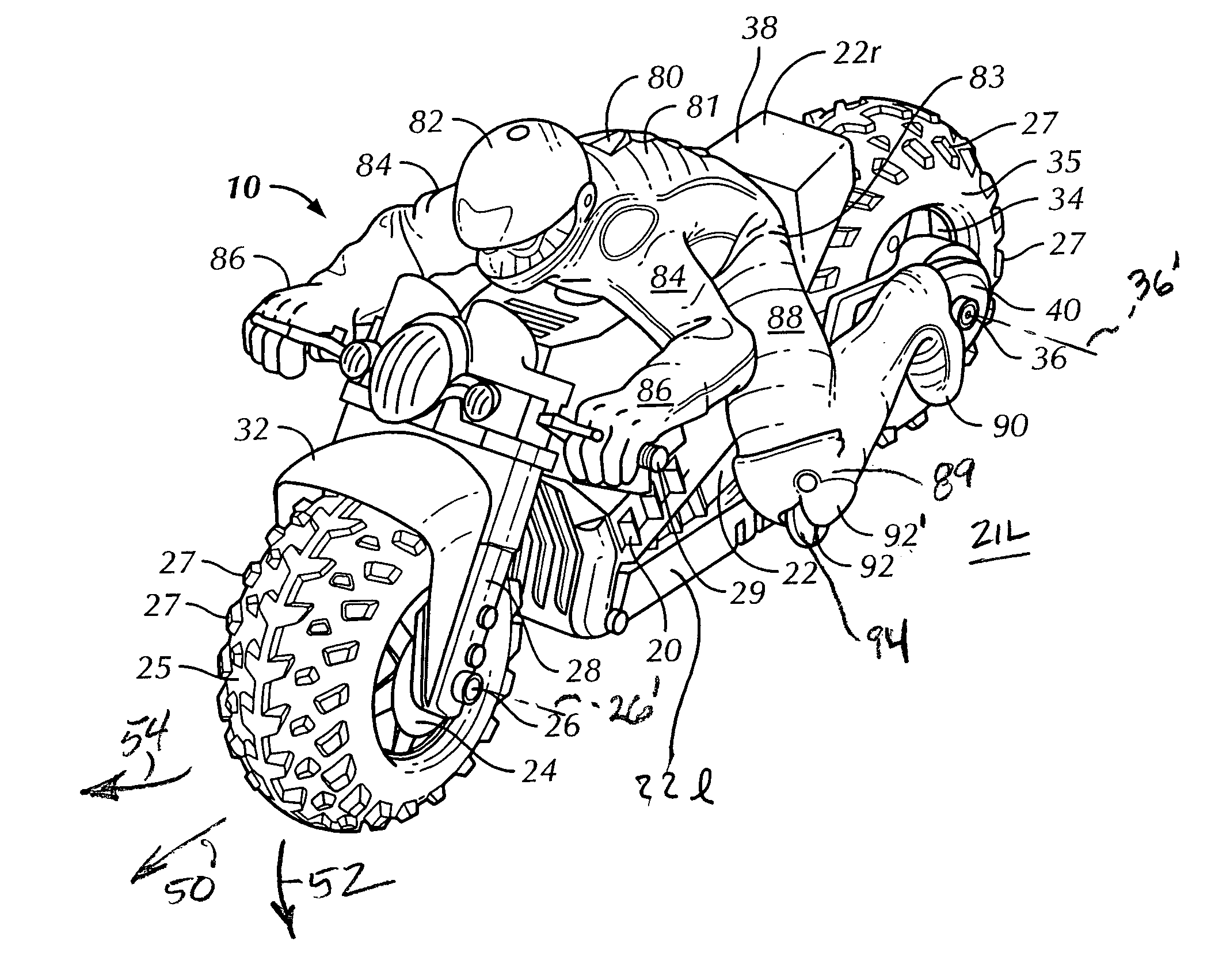
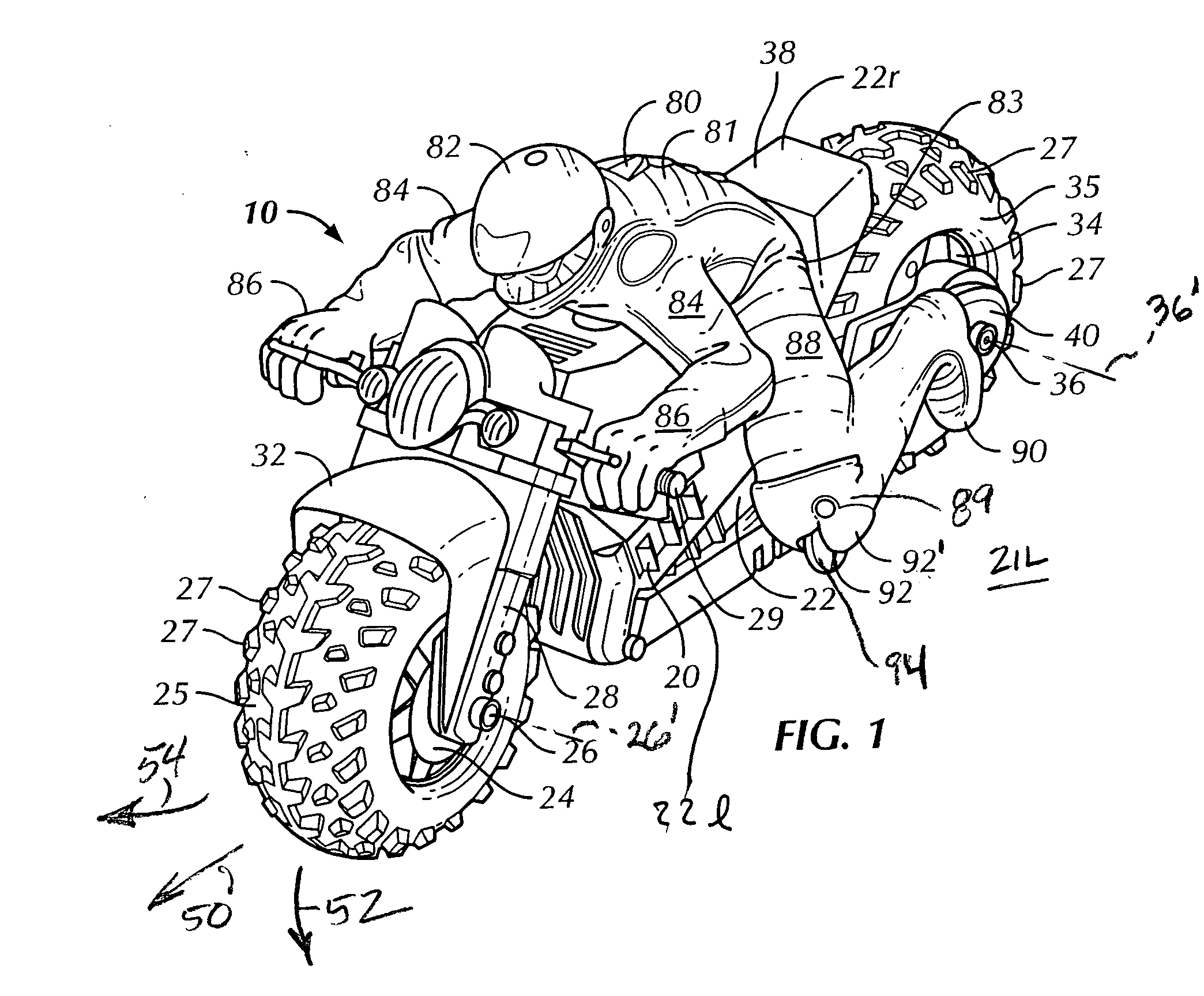
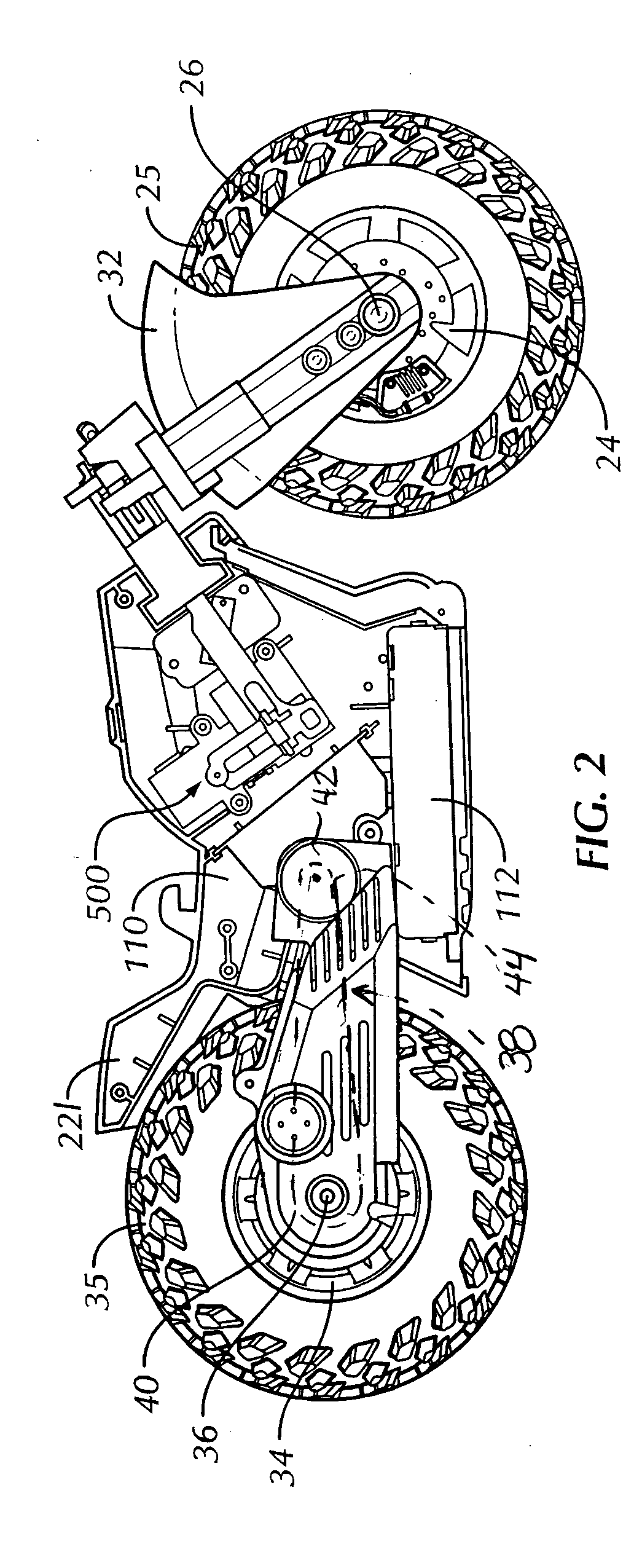
[0021] Referring to the drawings in detail, wherein like numerals indicate like elements throughout, there is shown in FIGS. 1-7 a presently preferred embodiment of a toy vehicle, in particular, a toy motorcycle 10 in accordance with the present invention. FIG. 8 illustrates an alternative steering assembly capable of being used with the toy motorcycle 10 or similar toys.

[0022] Referring to FIG. 1, the toy vehicle 10 comprises a vehicle “body” or “chassis” indicated generally at 20 and a single rider figurine (or simply “rider”) 80 attached thereto. The “chassis”20 may be the frame of a true frame and body construction or a combined frame and body housing ...


PUM


Abstract

A remote-controlled toy motorcycle includes a chassis supported by oversized front and rear tires for increased stability, and a chassis-mounted rider figure having rotating members for contacting a ground surface to prevent excessive wear of the rider figure legs and also to allow the toy motorcycle to self-start from a leaning position. “Counter-steering” is simulated by actuating a steering servo to initially turn a front wheel from a straight original direction to a direction opposite the desired turn direction. The front wheel is held momentarily while the toy motorcycle destabilizes and leans in the turn direction. Then, the steering servo is automatically actuated to turn the front wheel in the desired turn direction.

Description

CROSS-REFERENCE TO RELATED APPLICATIONS [0001] This application claims benefit of: U.S. Provisional Patent Application No. 60 / 622,205, “REBOUND MOTORCYCLE”, filed Oct. 26, 2004; U.S. Provisional Patent Application No. 60 / 642,466 “REBOUND SUPER BIKE”, filed Jan. 7, 2005; and U.S. Provisional Patent Application No. 60 / 696,498, “REMOTE-CONTROLLED MOTORCYCLE AND METHOD OF COUNTER-STEERING”, filed Jul. 1, 2005, all incorporated by reference.FIELD OF THE INVENTION [0002] The present invention relates generally to toy vehicles, and, more particularly, to remotely controlled, two-wheeled toy vehicles like motorcycles. BACKGROUND OF THE INVENTION [0003] Remote controlled, two-wheeled toys vehicles (i.e., motorcycles, motorbikes and scooters) are generally known. Among them are self-righting remote controlled motorcycles that maintain stability by having a wider tire in the rear. Although stability is increased, such motorcycles have difficulty staying upright at low speeds unless aided by an...

Claims


Application Information

Patent Timeline
08 Jun 2006
Publication
US20060121824A1
IPC
A63H17/21
CPC
A63H17/16; A63H17/21; A63H17/262; A63H17/36; A63H30/04
Inventors
LEE, CHUN WAH; VERBERA, STEVEN