
Method and device for determining acoustical transfer impedance

Inactive Publication Date: 2006-06-15
BRUEL & KJAER SOUND & MEASUREMENT
View PDF3 Cites 33 Cited by
  • Summary
  • Abstract
  • Description
  • Claims
  • Application Information

AI Technical Summary

Benefits of technology

[0014] Further, also vibration transducers such as accelerometers can be used instead of or in combination with measuring microphones. The use of vibration transducers in a forward or reverse path measurement makes it possible to measure the transfer function between mechanical excitation of a structure in a particular point and the sound level of the radiated sound in a “listening” position caused by the mechanical excitation.

Problems solved by technology

In complex structures with several noise sources, such as mentioned above, it can be complicated to identify noise sources and transmission paths and their contributions to the perceived noise.
However, when measuring the reverse transmission path with today's technology one still has to use a traditional sound source in the listening position, and traditional loudspeakers suffer form the drawback that they do not simulate any acoustic properties of a human being.

Method used


Image

  • Method and device for determining acoustical transfer impedance
  • Method and device for determining acoustical transfer impedance
  • Method and device for determining acoustical transfer impedance

Examples


Embodiment Construction

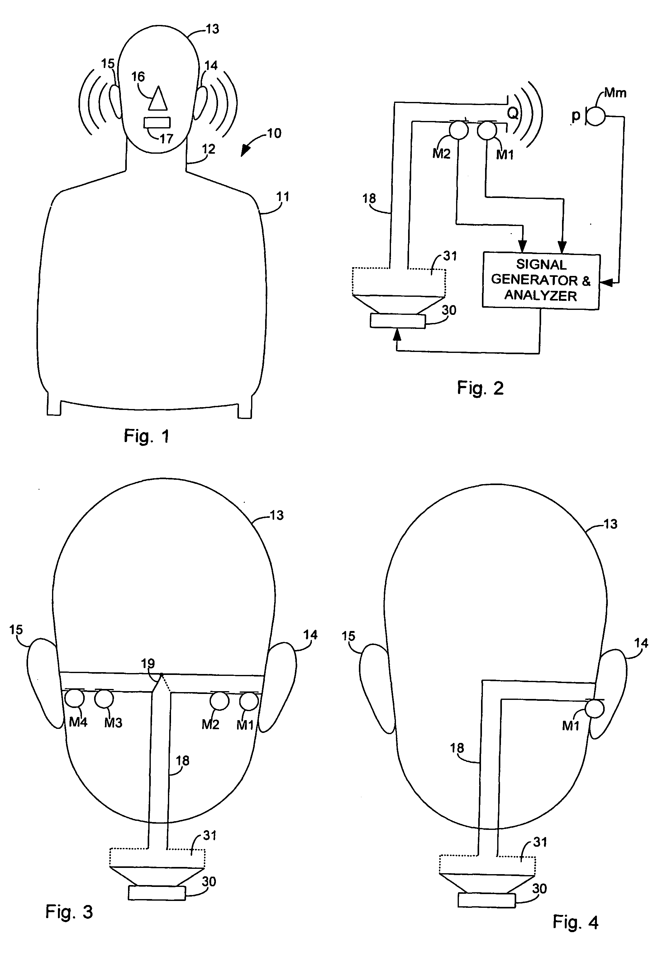
[0021] The invention is described with reference to the FIGS. 1-3. In the following, for simplicity all structures of the simulator that simulate portions of a human body are named as the corresponding human anatomical structures, which they are simulating. Thus, the structure of the simulator that simulates a human ear is referred to as an “ear” and not as a “simulated ear”.

[0022]FIG. 1 shows a front view of a simulator 10 with a torso 11 and neck 12 carrying a head 13. On the head the simulator has a left ear 14 and a right ear 15 each of which is shown with a pinna. Further, the head has a nose 16 and a mouth 17.

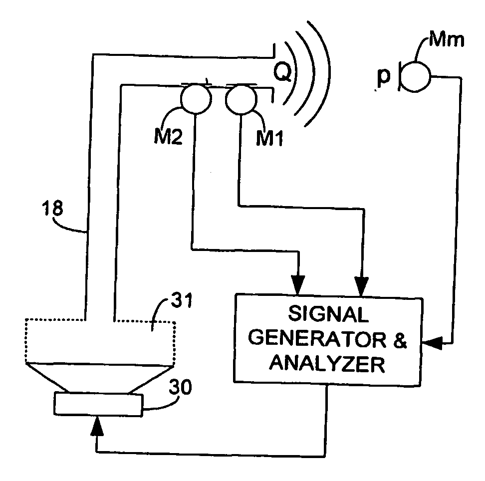
[0023]FIG. 3 shows schematically the interior of the head 13 of the simulator 10. Inside the simulator, preferably in the torso 11 or possibly in the neck 12, is a loudspeaker 30. The loudspeaker 30 is connected via a duct 18 to both ears 14 and 15. The duct 18 has a vertical portion and is branching like a “T” to the ears. The branching may also be in the form of a “Y”...


PUM


Abstract

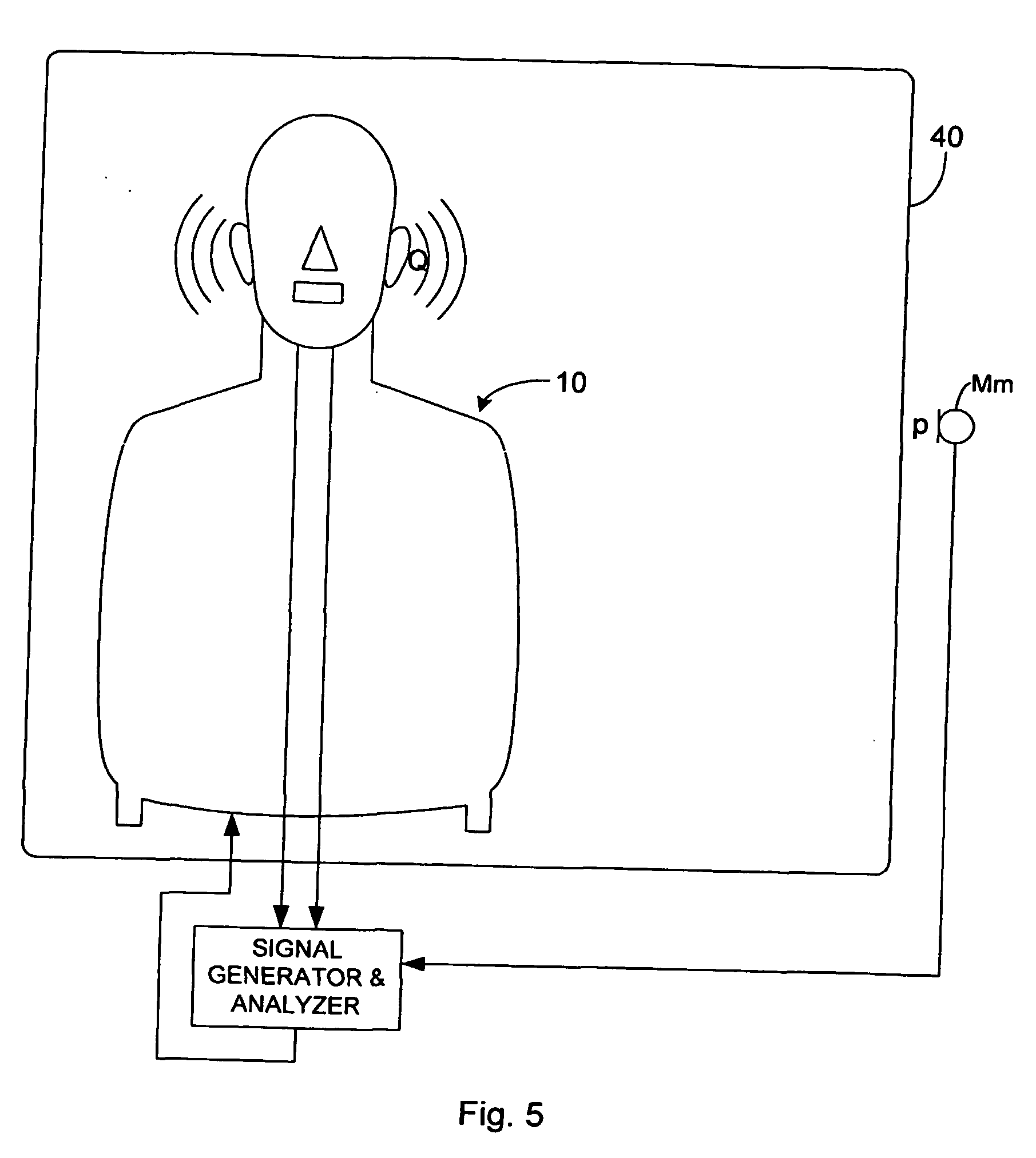
A method and device for determining acoustical transfer impedance The method comprises generating an acoustical volume velocity Q in the listening position, measuring a response quantity p, such as sound or vibration, at a suspected source position resulting from the volume velocity Q, and determining the acoustical transfer impedance Zt as the response quantity p divided by the acoustical volume velocity Q, Zt=p / Q. According to the invention the acoustical volume velocity Q is generated using a simulator (10) simulating acoustic properties of at least a head of a human being, the simulator comprising a simulated human ear (14, 15) with an orifice in the simulated head and a sound source (30) for outputting the acoustical volume velocity Q through the orifice. The output volume velocity Q from the orifice of an ear is estimated from measurements with two microphones inside the corresponding ear canal.

Description

FIELD OF THE INVENTION [0001] This invention relates to the investigation of transmission of sound from a sound source such as a noise source to a listening position of a human being. BACKGROUND OF THE INVENTION [0002] Protection of the environment and human beings has become more and more important. Buildings, cars, buses, aircraft, household appliances and industrial machinery have noise producing components such as engines, motors, gears, transmissions etc. In order to protect individuals from such noise, the noise generating components and the transmission path of the noise to a human being have been investigated with the purpose of reducing the generated noise at the source and of reducing the noise transmitted from the source to human beings. [0003] Testing of acoustic properties of noise generating and noise transmitting media such as mechanical structures and air or other fluids is an important part of the process of noise reduction. In complex structures with several noise ...

Claims


Application Information

Patent Timeline
IPC IPC(8): H04R29/00H04R3/00H04R5/027
CPCH04R5/027
Inventor GEIGER, KLAUSGLANDIER, CHRISTIANHELBER, ROLF
Owner BRUEL & KJAER SOUND & MEASUREMENT
Learn More