Method and apparatus reporting time-synchronized vehicular sensor waveforms from wireless vehicular sensor nodes

a vehicular sensor and wireless technology, applied in the field of wireless vehicular sensor networks, can solve the problems of difficult running wires to sensors embedded in roadways, difficult to report magnetic signatures, and often unreliable,

Inactive Publication Date: 2006-06-22
SENSYS NETWORKS
View PDF9 Cites 23 Cited by
  • Summary
  • Abstract
  • Description
  • Claims
  • Application Information

AI Technical Summary

Benefits of technology

[0007] Time synchronization supports a more rigorous analysis of the vehicular waveform reports, due to essentially the aligning the times of successive samples of the reports. Consider the example of the vehicle of FIG. 2A traversing near wireless vehicular sensor nodes, in particular the first wireless vehicular sensor node, followed by the second wireless vehicular sensor node, a third wireless vehicular sensor node, and a fourth wireless vehicular sensor node. FIG. 2B shows an example of what can happen without time synchronization, and 2C shows the effect of time synchronization as the time synchronized vehicular report, which is produced from the time synchronized system report. Without time synchronization, the views of the vehicle reported by the wireless vehicular sensor nodes are confused. With time synchronization, the vehicle can be seen clearly, in fact more clearly than any one sensor can show.
[0008] The use of time synchronization can be further seen in FIGS. 3A to 3C. FIG. 3A shows the first vehicular waveform report, the second vehicular waveform report, the third vehicular waveform report, and the fourth vehicular waveform report as they appear across time, in the time synchronized system report. FIG. 3B shows just the first vehicular waveform report and 3C shows the effect using the time synchronized system report to create the time synchronized vehicular report.

Problems solved by technology

While visual inspections can provide a good deal of information, they do not readily report the magnetic signature of a vehicle, which can reveal additional details about the vehicle contents.
The situation has some significant hurdles.
Running wires to sensors embedded in roadways turns out to be difficult, expensive, and often unreliable in the rugged environment of a roadway with multiple ton vehicles rolling over everything on a frequent basis.
These intermediate nodes are usually essentially invisible to the network, but add a significant delay to the time from the sending of the messages, and their reception at the collection node.
Additionally, a wireless vehicular sensor network may not provide a ready mechanism to time synchronizing these messages, making it difficult form an accurate picture of the magnetic signatures of the sensor state of these systems taken as a whole.

Method used


Image

  • Method and apparatus reporting time-synchronized vehicular sensor waveforms from wireless vehicular sensor nodes
  • Method and apparatus reporting time-synchronized vehicular sensor waveforms from wireless vehicular sensor nodes
  • Method and apparatus reporting time-synchronized vehicular sensor waveforms from wireless vehicular sensor nodes

Examples


Embodiment Construction

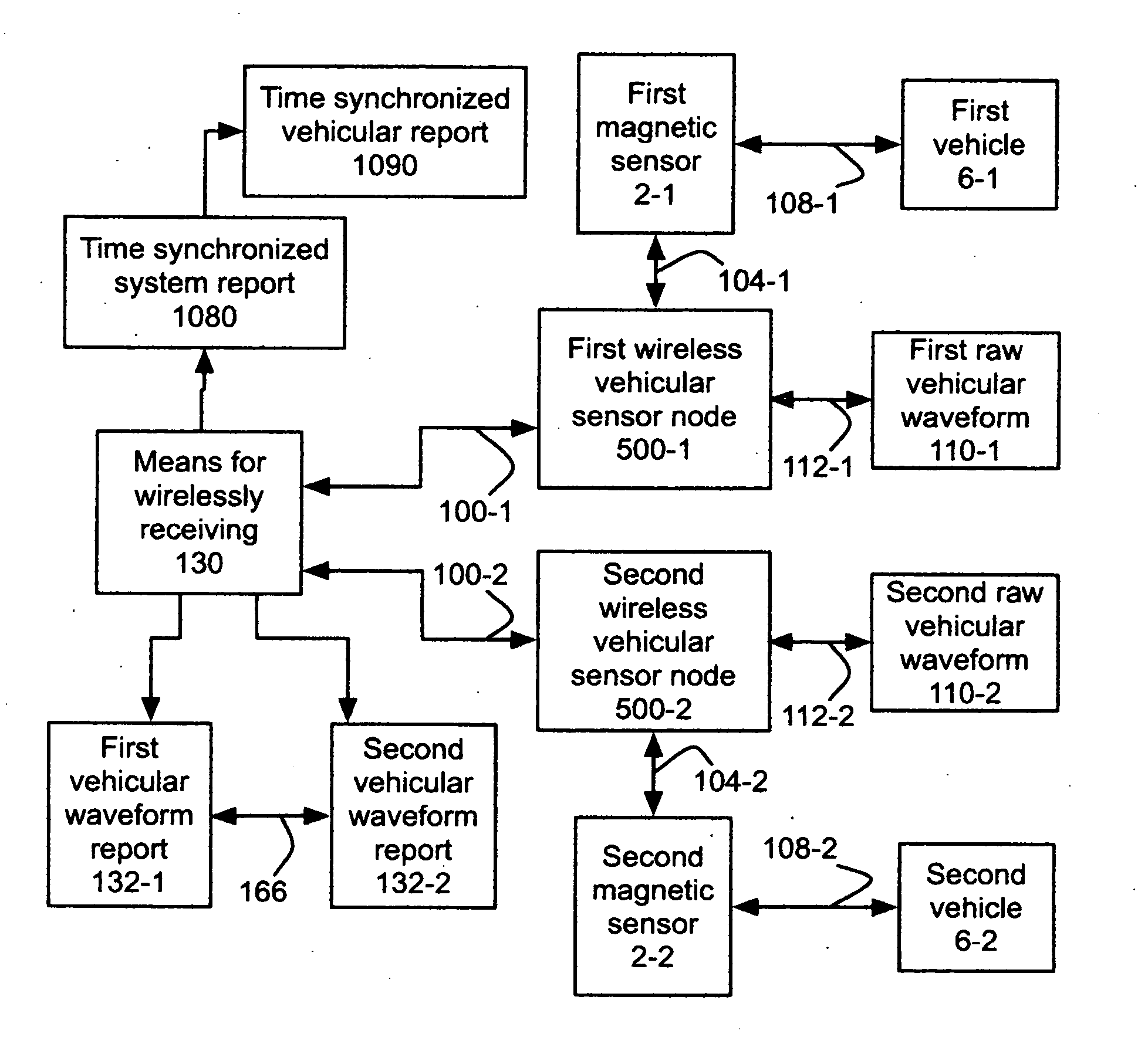
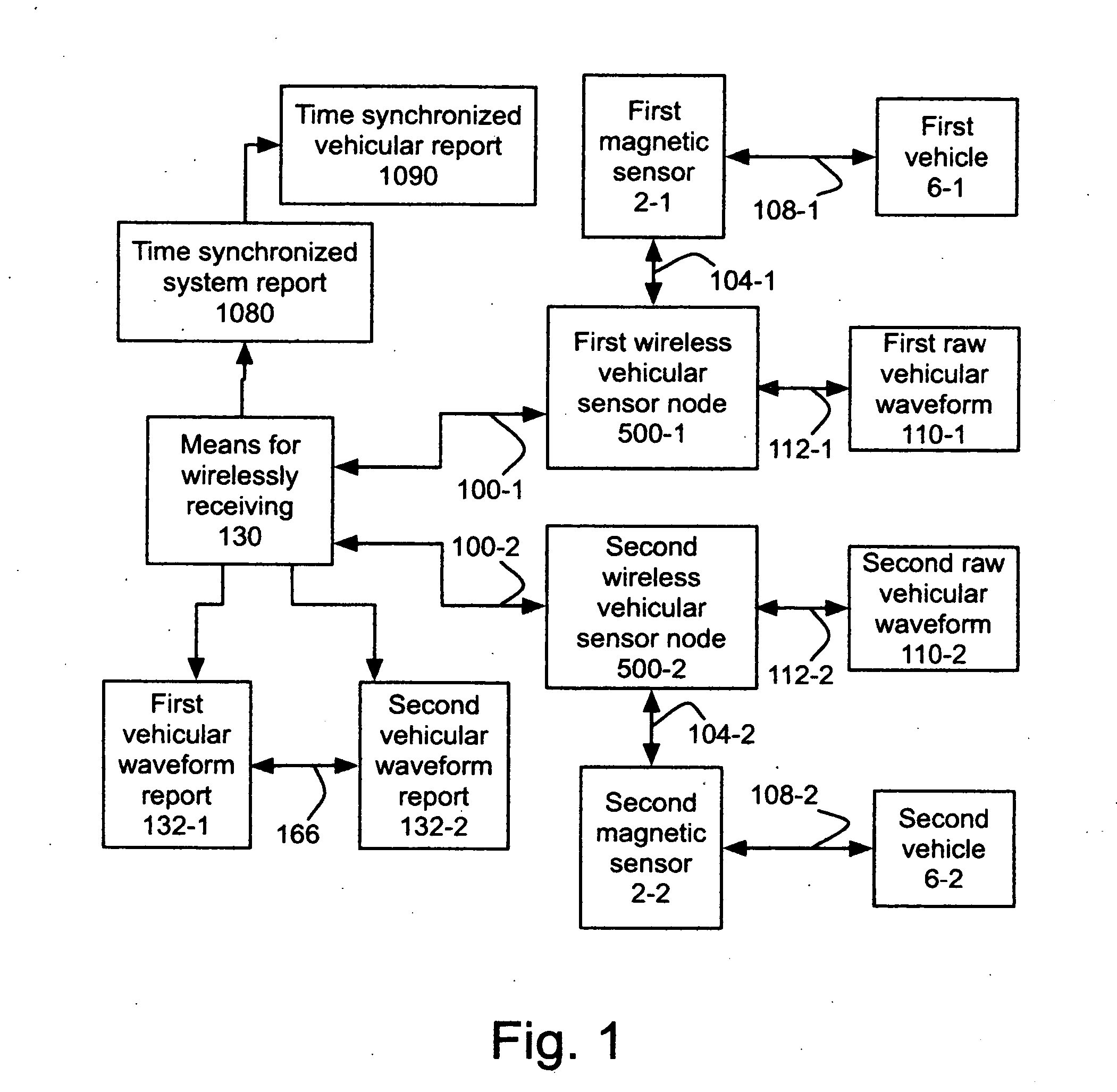
[0033] This invention relates to wireless vehicular sensor networks, in particular, to the reporting of the waveforms approximating the raw sensor readings due to the presence of motor vehicles. The invention includes using multiple wireless vehicular sensor nodes to wirelessly receive multiple time-synchronized vehicular waveform reports from the wireless vehicular sensor nodes. By way of example, the invention uses a first wireless vehicular sensor node 500-1 and a second wireless vehicular sensor node 500-2 to wirelessly receive 130 a first vehicular waveform report 132-1 from the first wireless vehicular sensor node time-synchronized 166 with a second vehicular waveform report 132-2 from the second wireless vehicular sensor node to create the time synchronized system report 1080 as shown in FIG. 1.

[0034] Time synchronization supports a more rigorous analysis of the vehicular waveform reports, due to essentially the aligning the times of successive samples of the reports. Consid...


PUM


Abstract

The invention includes using multiple wireless vehicular sensor nodes to wirelessly receive multiple, time-synchronized vehicular waveform reports from the nodes to create a time synchronized system report, and preferably a time synchronized vehicular report. Each vehicular waveform report approximates a raw vehicular sensor waveform observed by a magnetic sensor at the node based upon the presence of a vehicle. The vehicular waveform reports, the time-synchronized system report, and the time synchronized vehicular report are products of this wirelessly receiving process. The invention includes apparatus supporting the above outlined process. Reception of the vehicular waveform reports may be time interleaved.

Description

CROSS REFERENCES TO RELATED PATENT APPLICATIONS [0001] This application claims priority to Provisional Patent Application 60 / 695,742, filed on Jun. 29, 2005, and is also a continuation in part of U.S. patent application Ser. No. 11 / 062,130, filed Feb. 19, 2005, which claims priority to Provisional Patent Application Ser. No. 60 / 549,260, filed. Mar. 1, 2004 and Provisional Patent Application Ser. No. 60 / 630,366, filed Nov. 23, 2004, all of which are incorporated herein by reference.TECHNICAL FIELD [0002] This invention relates to wireless vehicular sensor networks, in particular, to the reporting of the waveforms approximating the raw sensor readings due to the presence of motor vehicles. BACKGROUND OF THE INVENTION [0003] Today, there are numerous situations in which confirming the type of vehicle passing over a spot on the road is important. While visual inspections can provide a good deal of information, they do not readily report the magnetic signature of a vehicle, which can rev...

Claims


Application Information

Patent Timeline
Patent Type & Authority Applications(United States)
IPC IPC(8): G08B19/00B60R25/10G08B1/08G08G1/01G07B15/02
CPCG03B21/10G03B21/28G08G1/042H04N5/74H04N9/3141
Inventor KAVALER, ROBERT
Owner SENSYS NETWORKS
Why Eureka
Try Eureka