Removable abradable seal carriers for sealing between rotary and stationary turbine components

a technology of abradable seals and seal surfaces, which is applied in the direction of machines/engines, stators, liquid fuel engines, etc., can solve the problems of reducing turbine efficiency, affecting sealing, and difficult to create seals,

Active Publication Date: 2006-06-22
GENERAL ELECTRIC CO
View PDF15 Cites 44 Cited by
  • Summary
  • Abstract
  • Description
  • Claims
  • Application Information

AI Technical Summary

Problems solved by technology

These clearances are, of course, detrimental to sealing.
There are also clearance issues associated with multiple independent seal surfaces, tolerance stack up of radial clearances and assembly of multiple seals, all of which can diminish turbine efficiency.
Moreover, it is often difficult to create seals which not only increase the efficiency of the steam turbine but also increase the ability to service and repair various parts of the turbine as well as to create known repeatable boundary conditions for such parts.

Method used


Image

  • Removable abradable seal carriers for sealing between rotary and stationary turbine components
  • Removable abradable seal carriers for sealing between rotary and stationary turbine components
  • Removable abradable seal carriers for sealing between rotary and stationary turbine components

Examples


Embodiment Construction

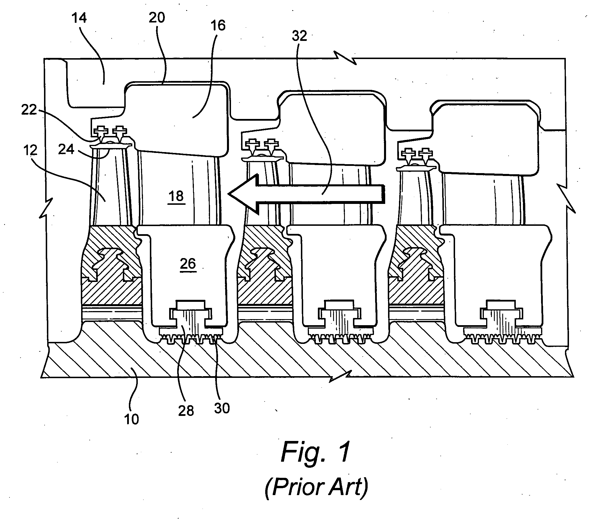
[0009] Referring now to the drawing figures, particularly to FIG. 1, there is illustrated a portion of a steam turbine having a rotary component, for example a rotor 10 mounting a plurality of circumferentially spaced buckets 12 at spaced axial positions along the turbine forming parts of the various turbine stages and a stationary component 14 including a plurality of diaphragms 16 mounting partitions 18 defining nozzles which, together with respective buckets, form the various stages of the turbine. As illustrated, the outer ring 20 of the diaphragm 16 carries one or more rows of seal teeth 22 for sealing with the shrouds or covers 24 adjacent the tips of buckets 12. Similarly, the inner ring 26 of diaphragm 16 mounts an arcuate seal segment 28. The seal segment has radially inwardly projecting high-low teeth 30 for sealing with the rotary component 10. Similar seals are provided at the various stages as illustrated and the direction of steam flow is indicated by the arrow 32.

[00...


PUM


Abstract

The turbine includes a diaphragm having a seal carrier mounted in opposition to seal teeth carried by the rotary component. The seal carrier includes a seal face having a coating of abradable material enabling the rotary component to abrade the material from the seal face. The seal carrier is removable from the diaphragm and is carried by an axial extension integral with or removable from the outer diaphragm ring. A spring may be interposed between the seal carrier and the stationary component.

Description

BACKGROUND OF THE INVENTION [0001] The present invention relates to seals between rotatable and stationary components of a turbine and particularly relates to removable seal carriers having abradable seal surfaces for sealing between rotatable and stationary turbine components. [0002] In turbines particularly steam turbines, seals between rotary and stationary components are a critical part of the steam turbine performance. It will be appreciated that the greater the number and magnitude of steam leakage paths, the greater the losses of efficiency of the steam turbine. For example, labyrinth seal teeth often used to seal between the diaphragms and the rotor or between the rotor bucket tips and the stationary shroud require substantial clearances to be maintained to allow for radial and circumferential movement during transient operations such as startup and shutdown. These clearances are, of course, detrimental to sealing. There are also clearance issues associated with multiple ind...

Claims


Application Information

Patent Timeline
Patent Type & Authority Applications(United States)
IPC IPC(8): F01D5/20
CPCF01D5/225F01D11/001F01D11/122
Inventor BRACKEN, ROBERT JAMESHATHAWAY, STERLING RAYFITTS, DAVID ORUSKORZUN, RON W.DUCLOS, LAURENCE SCOTTADIS, WILLIAM EDWARDKOWALCZYK, MARK WILLIAMCOUTURE, BERNARD ARTHUR
Owner GENERAL ELECTRIC CO
Why Eureka
Try Eureka