Counterflow thermoelectric configuration employing thermal transfer fluid in closed cycle

a technology of thermal transfer fluid and counterflow, which is applied in the direction of machines using electric/magnetic effects, lighting and heating apparatus, refrigerating machines, etc. it can solve the problems of affecting the performance of the device, malfunctioning or breaking of the device, and generating substantial heat during operation of the electronic device, so as to achieve cost-effective use, large array configuration, and high heat flux density device

Active Publication Date: 2006-06-29
SHEETAK INC
View PDF62 Cites 50 Cited by
  • Summary
  • Abstract
  • Description
  • Claims
  • Application Information

AI Technical Summary

Benefits of technology

[0008] Active cooling technologies such as thermoelectrics can be used to introduce thermal “gain” into a cooling system and, when employed in combination with forced flow liquid metal cooling loops, can provide an attractive solution for cooling high heat flux density devices and / or components. Total cooling power can be increased by employing multiple thermoelectric elements. Indeed, by employing modem semiconductor technologies, including e.g., thin-film technologies, thermoelectric elements may be cost-effectively employed and configured in large arrays.

Problems solved by technology

Electronic devices such as central processing units, graphic-processing units and laser diodes can generate substantial heat during operation.
If such heat is not dissipated properly, temperature buildup may occur and such buildup can adversely affect the performance of these devices.
For example, excessive temperature buildup may lead to malfunctioning or breakdown of the devices.
Alternatively, stability or performance characteristics may be adversely affected.
While ever larger heat sinks and forced air techniques can be employed to improve dissipation to the ambient environment, form factor or other constraints may limit these solutions.

Method used


Image

  • Counterflow thermoelectric configuration employing thermal transfer fluid in closed cycle
  • Counterflow thermoelectric configuration employing thermal transfer fluid in closed cycle
  • Counterflow thermoelectric configuration employing thermal transfer fluid in closed cycle

Examples


Embodiment Construction

)

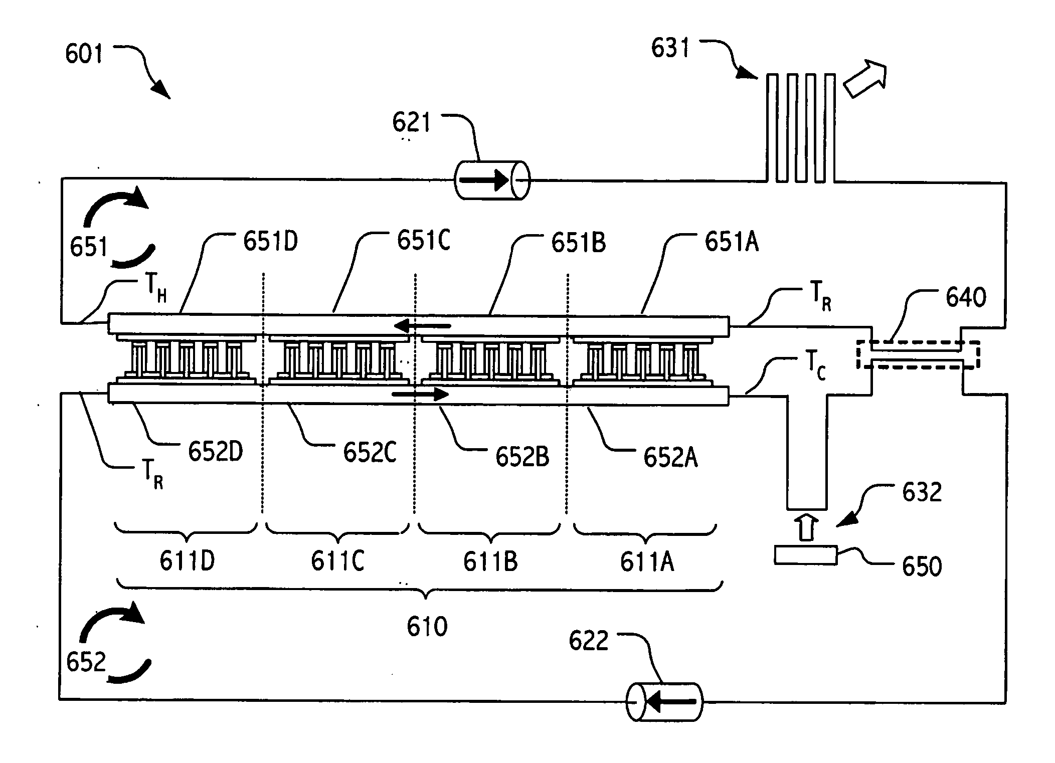
[0030] In the description that follows, we detail systems that employ arrays of thermoelectric modules in conjunction with one or more closed fluid cycle loops in which a forced flow of thermal transfer fluid (e.g., a liquid metal thermal transfer fluid) is used to transfer thermal energy to or from the thermoelectric modules. Topologies of the thermal transfer fluid flows are designed to provide substantially uniform thermal differentials across respective ones of the thermoelectric modules. In cooling (or heating) configurations, such topologies provide substantially uniform thermal differentials across thermoelectric modules of an array and allow each of the thermoelectric modules to operate in a desired efficiency regime, while accumulating in the thermal transfer fluid flow the heat transfer contributed by each of the thermoelectric modules.

[0031] Thermoelectric devices and materials are well-known in the art and a wide variety of configurations, systems and exploitations the...


PUM


Abstract

Active cooling technologies such as thermoelectrics can be used to introduce thermal “gain” into a cooling system and, when employed in combination with forced flow liquid metal cooling loops, can provide an attractive solution for cooling high heat flux density devices and / or components. Total cooling power can be increased by employing multiple thermoelectric elements. Indeed, by employing modern semiconductor technologies, including e.g., thin-film technologies, thermoelectric elements may be cost-effectively employed and configured in large arrays.

Description

BACKGROUND [0001] 1. Field of the Invention [0002] The present invention relates to thermal transfer systems, and more particularly, to thermoelectric array configurations in which counterflows of a thermal transfer fluid are employed in a closed-cycle thermal transfer system. [0003] 2. Description of the Related Art [0004] Electronic devices such as central processing units, graphic-processing units and laser diodes can generate substantial heat during operation. If such heat is not dissipated properly, temperature buildup may occur and such buildup can adversely affect the performance of these devices. For example, excessive temperature buildup may lead to malfunctioning or breakdown of the devices. Alternatively, stability or performance characteristics may be adversely affected. Accordingly, it is important to remove the generated heat in order to maintain desired operating temperatures of these devices. [0005] In many challenging scientific and commercial cooling applications, ...

Claims


Application Information

Patent Timeline
Patent Type & Authority Applications(United States)
IPC IPC(8): F25B21/02
CPCF25B21/02F25B25/005F25B2321/0252H01L35/30H01L35/32H10N10/17H10N10/13
Inventor GHOSHAL, UTTAM
Owner SHEETAK INC
Why Eureka
Try Eureka