Remotely positionable and magnetically attachable securement device
Inactive Publication Date: 2006-06-29
CLEMENT JOE RAYMOND
View PDF2 Cites 18 Cited by
- Summary
- Abstract
- Description
- Claims
- Application Information
AI Technical Summary
Benefits of technology
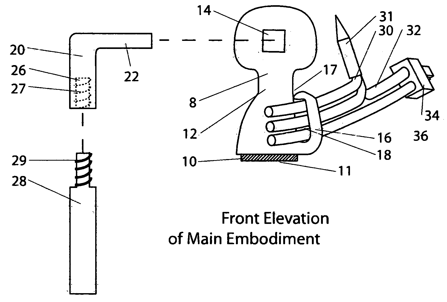
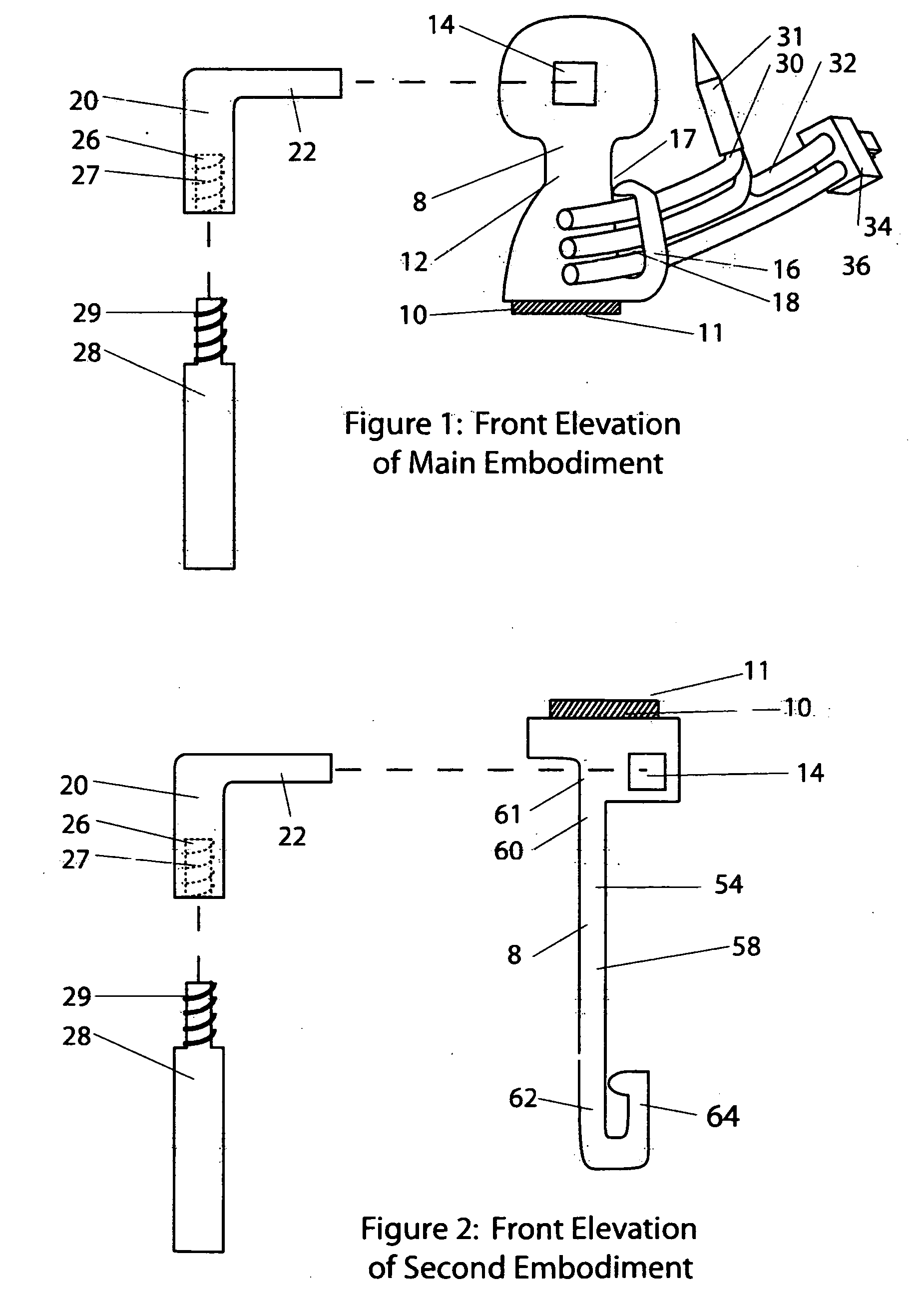
[0014] The remote hanging of the magnetic securement device for a decorative light strand is safer than placing the traditional eave hanger because the use of a ladder is eliminated. Through the use of the attachable extension pole the mag
Problems solved by technology
Stability problems often result from such use.
Accidents can happen in these situations.
The task is laborious, time consuming, difficult, and even dangerous.
The addition of hooks often leaves permanent holes and the hooks may also rust and stain the building.
The unsightly hooks or wires are often left on year round due to the difficulty or removing them and replacing them each holiday season.
The attachment of these hooks and wires often takes place during frigid weather and this adds to the discomfort and time required to perform this task.
Gloves must often be worn and this causes the job to be prolonged.
When the lights are to be suspended from elevated objects such as eaves, trees, or lamp posts an element of risk is added.
Frozen and icy ground conditions add an element of risk to this task.
However it is still time consuming and irksome.
Tape, hooks and wires are the most common means of attachment but they can all leave
Method used
View moreImage
Smart ImageViewing Examples
Examples
Example
[0018]FIG. 2: Front Elevation of Second Embodiment
Example
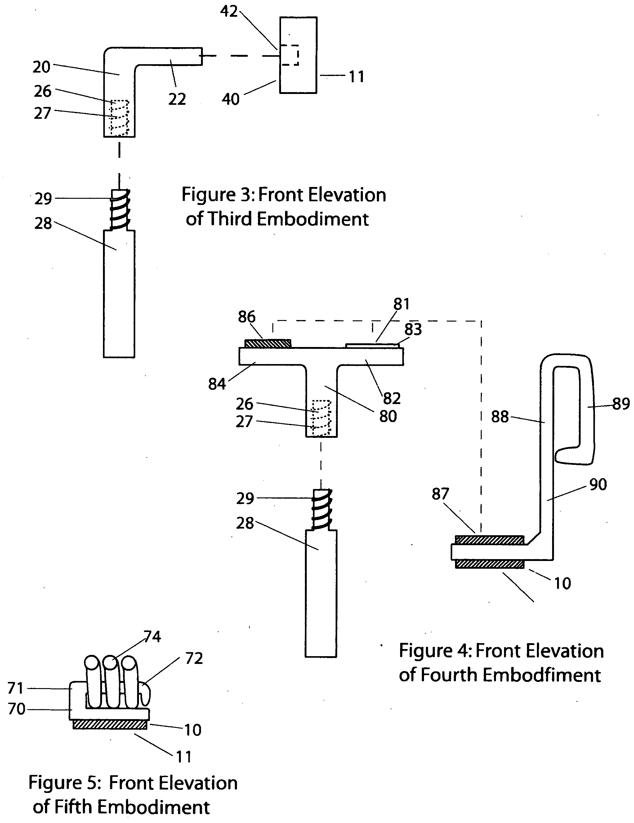
[0019]FIG. 3: Front Elevation of Third Embodiment
Example
[0020]FIG. 4: Front Elevation of Fourth Embodiment
Login to View More PUM
 Abstract
An improved magnetic securing device that incorporates a neodymium magnet, a securing member, and a means of remote placement. The remote placement is intended to be manual and may be accomplished by magnetic or physical mating to a pole used for extending the reach of the person placing the device. The securing member may be a clip, hook, confining passageway, or other. If a securing member is not provided, objects desired to be secured to the remotely hung device could be permanently affixed.
Description
BACKGROUND [0001] 1. Field of Invention [0002] This invention relates to the field of magnetically supporting objects that are desired to be displayed on a ferric surface. [0003] 2. Description of Prior Art [0004] The need to secure objects to vertical or overhead surfaces in everyday life is common. Our walls and ceilings are hung with a host of objects from calendars and clocks to photos and maps. Ferric surfaces exist in many locations in our environs. These include cabinets, inboxes, computer cases, window jambs and a host of other objects. The availability of these ferric surfaces provides the opportunity to magnetically hang objects desired to be displayed on them. This is an opportunity because magnetic securing devices provide many advantages over nails and adhesives that make up the bulk of hangers. Magnets can be easily applied and removed. They are inexpensive and they leave no scar or residue behind. They allow a great flexibility of display and many types and sizes are ...
Claims
Login to View More Application Information
Patent Timeline
 IPC IPC(8): A47G1/17
CPCF21S4/001F21V19/04F21V21/096F21W2121/00F21S4/10
Inventor CLEMENT, JOE RAYMOND
Owner CLEMENT JOE RAYMOND
Features
- R&D
- Intellectual Property
- Life Sciences
- Materials
- Tech Scout
- Unparalleled Data Quality
- Higher Quality Content
- 60% Fewer Hallucinations
Learn More Browse by: Latest US Patents, China's latest patents, Technical Efficacy Thesaurus, Application Domain, Technology Topic, Popular Technical Reports.
© 2025 PatSnap. All rights reserved.Legal|Privacy policy|Modern Slavery Act Transparency Statement|Sitemap|About US| Contact US: help@patsnap.com


