Common mode surge protection filter

a filter and common-mode technology, applied in emergency protective arrangements for limiting excess voltage/current, electrical equipment, etc., can solve problems such as limited life during high-energy transients, increased difficulty of current leakage, and easy failure of united laboratories

Inactive Publication Date: 2006-06-29
HEWLETT PACKARD DEV CO LP
View PDF15 Cites 54 Cited by
  • Summary
  • Abstract
  • Description
  • Claims
  • Application Information

AI Technical Summary

Problems solved by technology

A problem with usage of bulk capacitance, such as Y-capacitors, for common mode protection is susceptibility to failing United Laboratories, Inc.
The higher the capacitance level that is sufficient to absorb the higher energies, the greater the difficulty of current leakage becomes.
The problem with gas discharge tubes (GDT) is limited life during high energy transients.
GDT implementations eventually fail leaving a device unprotected.

Method used


Image

  • Common mode surge protection filter
  • Common mode surge protection filter
  • Common mode surge protection filter

Examples


Embodiment Construction

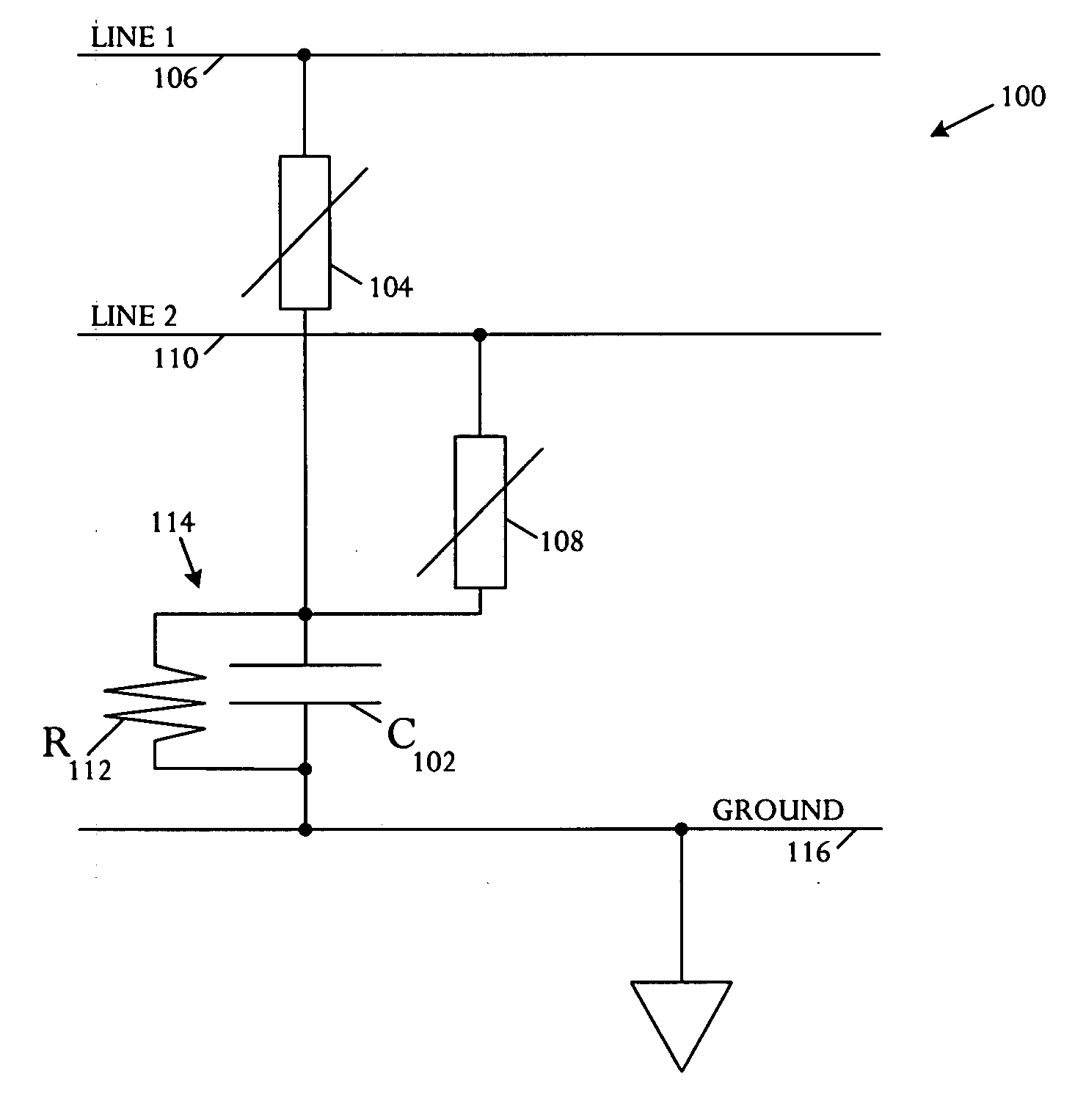
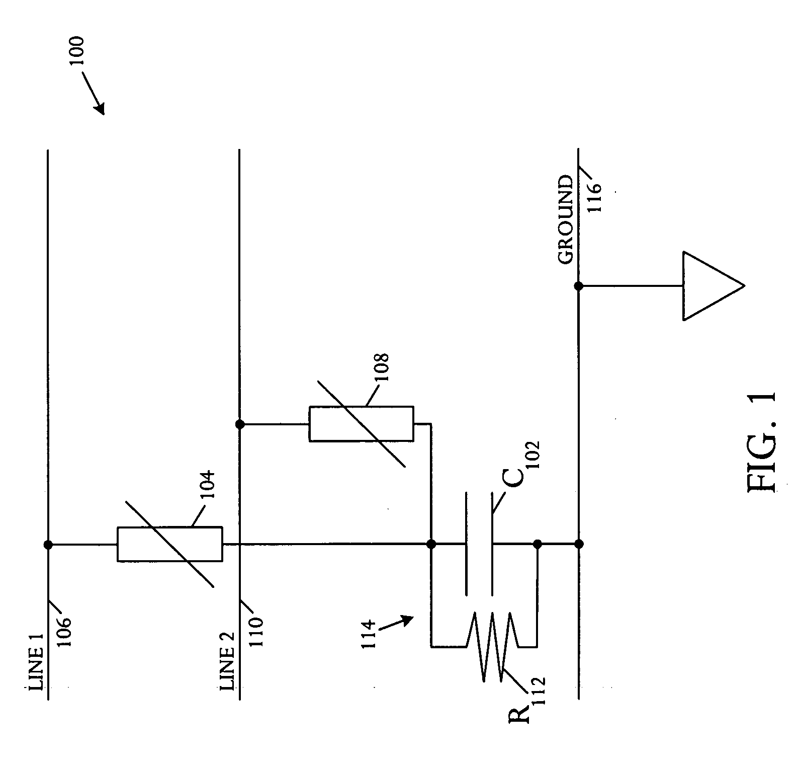
[0011] Referring to FIG. 1, a schematic circuit diagram illustrates an embodiment of a filter circuit 100 for common mode surge protection. The filter circuit 100 comprises a Y-capacitor 102, a first metal oxide varistor (MOV) 104 coupled between a first line 106 and the Y-capacitor 102, and a second metal oxide varistor (MOV) 108 coupled between a second line 110 and the Y-capacitor 102. The circuit 100 includes a metal oxide varistor (MOV) 104, 108 on each inlet line 106, 110. Both metal oxide varistors 104, 108 terminate onto the Y-capacitor 102.

[0012] A resistor 112 is coupled in parallel with the Y-capacitor 102 and the resulting resistor-capacitor (RC) parallel circuit 114 is connected to ground 116. The Y-capacitor 102 has a resistor R 112 in parallel to assist in discharging the Y-capacitor 102 upon the occurrence of any transient voltage spike or surge that charges the Y-capacitor 102. Both the Y-capacitor 102 and the resistor R 112 terminate to chassis ground 116.

[0013] ...


PUM


Abstract

A filter circuit in a surge protection device comprises a Y-capacitor, a first metal oxide varistor (MOV) coupled between a first line and the Y-capacitor, and a second metal oxide varistor (MOV) coupled between a second line and the Y-capacitor.

Description

BACKGROUND OF THE INVENTION [0001] Common mode high voltage transients are typically protected by bulk capacitance, Y-capacitors, gas discharge tubes (GDT), or a combination of metal oxide varistors (MOVs) and GDTs. A problem with usage of bulk capacitance, such as Y-capacitors, for common mode protection is susceptibility to failing United Laboratories, Inc. (UL) current leakage testing. The higher the capacitance level that is sufficient to absorb the higher energies, the greater the difficulty of current leakage becomes. [0002] The problem with gas discharge tubes (GDT) is limited life during high energy transients. GDT implementations eventually fail leaving a device unprotected. [0003] Metal oxide varistors (MOVs) alone are not used for common mode protection due to regulatory high potential (Hi-pot) specifications. Thus, MOVs are commonly used in combination with GDTs or used in differential mode alone. SUMMARY [0004] In accordance with a surge protection device, an embodiment...

Claims


Application Information

Patent Timeline
Patent Type & Authority Applications(United States)
IPC IPC(8): H02H9/00
CPCH02H9/042
Inventor YATES, KIRKCHERNISKI, ANDREW MICHAELVILORIA, KENNETH
Owner HEWLETT PACKARD DEV CO LP
Why Eureka
Try Eureka