Apparatus and method for transmitting/receiving channel quality information in a communication system
a communication system and channel technology, applied in the field of communication systems, can solve the problems of increasing the probability of transmission error, waste of radio resources, etc., and achieve the effect of efficient allocation of radio resources
- Summary
- Abstract
- Description
- Claims
- Application Information
AI Technical Summary
Benefits of technology
Problems solved by technology
Method used
Image
Examples
first embodiment
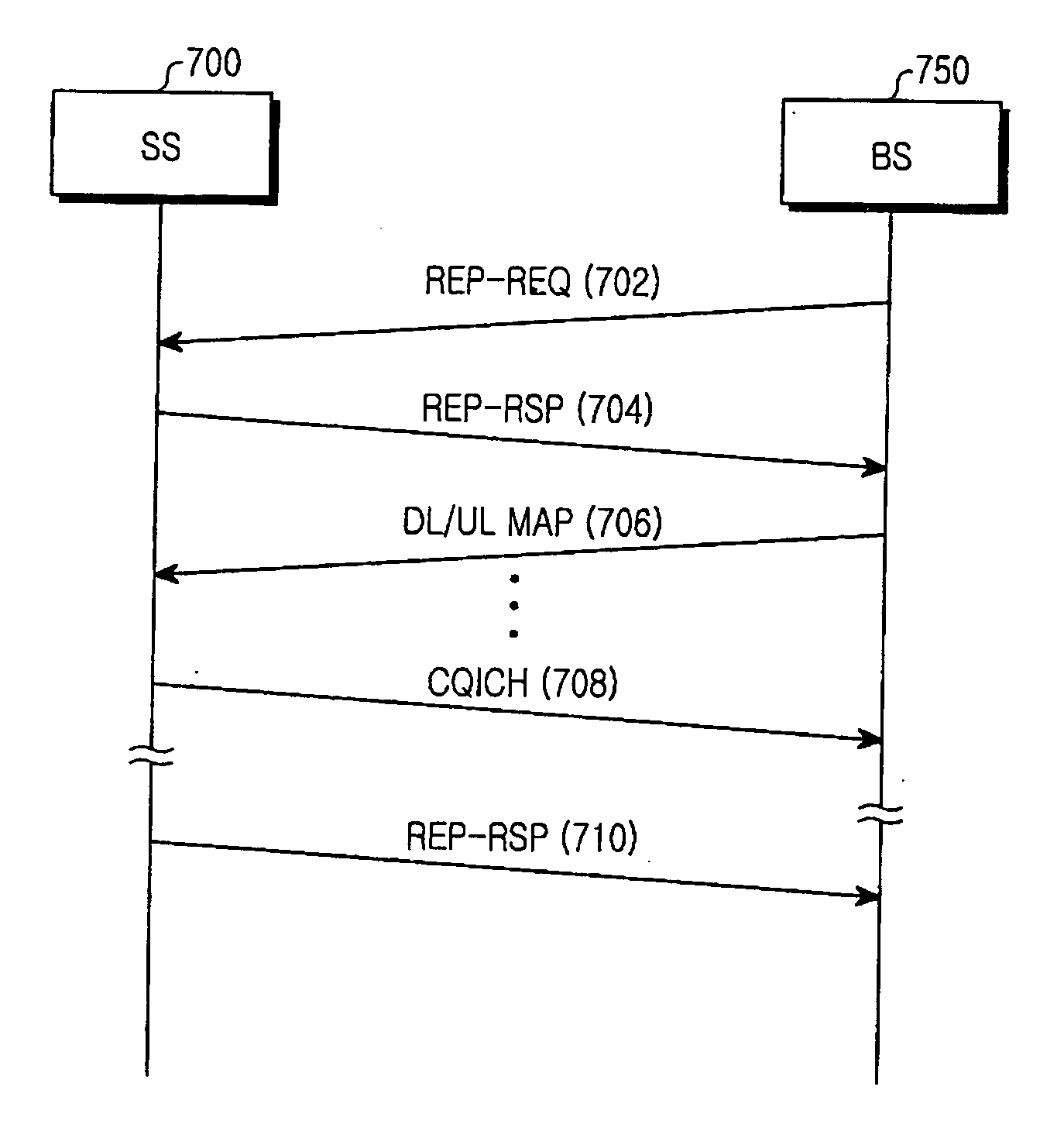
[0060] Table 1 below shows Type Length Value (TLV) parameters in a REP-REQ message according to a first embodiment of the present invention, in which the length is expressed in bytes.
TABLE 1NameTypeLengthValueChannel1.31Bit #0 = 1: Report the (equivalent) estimationTypeof CINR in PUSC region with frequencyRequestreuse factor = 3,Bit #1 = 1: Report the (equivalent) estimationof CINR in PUSC region with frequencyreuse factor = 1,Bit #2 = 1: Report the (equivalent) estimationof CINR in FUSC region,Bit #3 = 1: Report the (equivalent) estimationof CINR in Optional FUSC region,Bit #4 = 1: Report the (equivalent) estimationof CINR in Band AMC Channel region,Bit #5 = 1: Report the (equivalent) estimationof CINR in Safety Channel region,Bit #6 = 1: Reserved,Bit #7: AAS CINR measurement indicator:When the last bit of Channel Type request is‘0’ the CINR measurement directed by Bit#4 shall be done for the symbols that are notbeamformed. Otherwise, the CINRmeasurement directed by Bit #4 shall ...
second embodiment
[0067] Table 3 below shows TLV parameters in a REP-REQ message according to a second embodiment of the present invention, in which the length is expressed in bytes.
TABLE 3NameTypeLengthValueChannel1.31Bit #0: CINR for reuse 1 configurationTypeBit #1: CINR for reuse K configurationRequestBit #2: CINR for Band AMC ZoneBit #3: CINR of Safety ChannelBit #4˜6: reserved.Bit #7: AAS CINR measurement indicator:When the last bit of Channel Type Request is‘0’ the CINR measurement directed by Bit #4shall be done for the symbols that are notbeamformed. Otherwise, the CINRmeasurement directed by Bit #4 shall be donefor the symbols that are beamformed.
[0068] As described above, in the second embodiment, a BS instructs an SS to report CQIs for subchannels associated with frequency reuse factors ‘1’ and ‘K’, and the SS measures CQIs or equivalent CQIs for the subchannels associated with the frequency reuse factors ‘1’ and ‘K’, and reports the measured CQIs to the BS. Therefore, compared with the ...
third embodiment
[0072] Table 5 below shows TLV parameters in a REP-REQ message according to a third embodiment of the present invention, in which the length is expressed in bytes.
TABLE 5NameTypeLengthValueChannel1.31000 = Normal subchannel with frequency reuseTypefactor = 1 configuration,Request001 = Normal subchannel with frequency reusefactor = K configuration (K is positive intergergreater than one),010 = -Band AMC Channel011 = Safety Channel,Bit #3˜6: reserved.Bit #7: AAS CINR measurement indicator:When the last bit of ChannelType Request is ‘0’ theCINR measurement directed by Bit #4 shall bedone for the symbols that are not beamformed.Otherwise, the CINR measurement directed byBit #4 shall be done for the symbols that arebeamformed.
[0073] As described above, in the third embodiment, a BS can allocate subchannels associated with one frequency reuse factor for an individual SS according to an operation environment. Therefore, the BS can instruct the SS to report only the CQIs for the subchanne...
PUM
 Abstract
Description
Claims
Application Information
 - R&D
- Intellectual Property
- Life Sciences
- Materials
- Tech Scout
- Unparalleled Data Quality
- Higher Quality Content
- 60% Fewer Hallucinations
Browse by: Latest US Patents, China's latest patents, Technical Efficacy Thesaurus, Application Domain, Technology Topic, Popular Technical Reports.
© 2025 PatSnap. All rights reserved.Legal|Privacy policy|Modern Slavery Act Transparency Statement|Sitemap|About US| Contact US: help@patsnap.com


