Vacuum cleaner with cyclonic separating dirt cup and dirt cup door

a vacuum cleaner and cyclonic technology, applied in the field of vacuum cleaners, can solve the problems of clogging of debris, small filter elements, and suffering of above-mentioned hand-held vacuum cleaners, and achieve the effects of reducing the number of clogged debris, reducing the efficiency of cleaning, and improving the cleaning efficiency

Inactive Publication Date: 2006-07-20
ROYAL APPLIANCE MFG
View PDF27 Cites 207 Cited by
  • Summary
  • Abstract
  • Description
  • Claims
  • Application Information

AI Technical Summary

Problems solved by technology

However, the above mentioned hand-held vacuum cleaners suffer a number of disadvantages.
One disadvantage is that the filter elements are often small and tend to clog with debris relatively quickly.
This disadvantage arises as a result of the compact nature of these hand-held vacuum cleaners.
Thus, the overall vacuum and pickup efficiency of the cleaner is reduced as well.
Another disadvantage with prior hand-held vacuum cleaners is that they do not provide a convenient method of emptying the dirt which accumulates in the dirt cup of the cleaner.

Method used


Image

  • Vacuum cleaner with cyclonic separating dirt cup and dirt cup door
  • Vacuum cleaner with cyclonic separating dirt cup and dirt cup door
  • Vacuum cleaner with cyclonic separating dirt cup and dirt cup door

Examples


Embodiment Construction

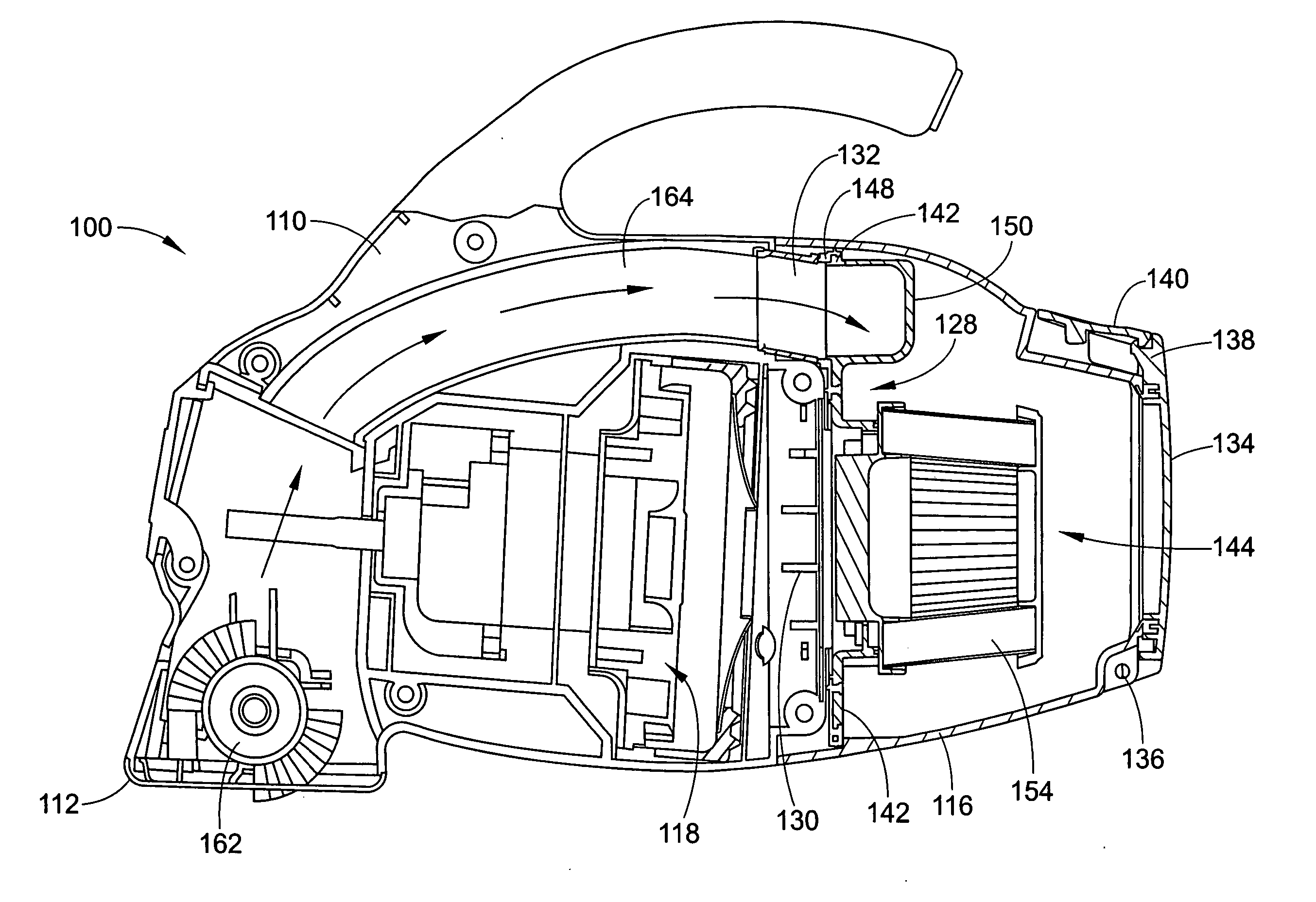
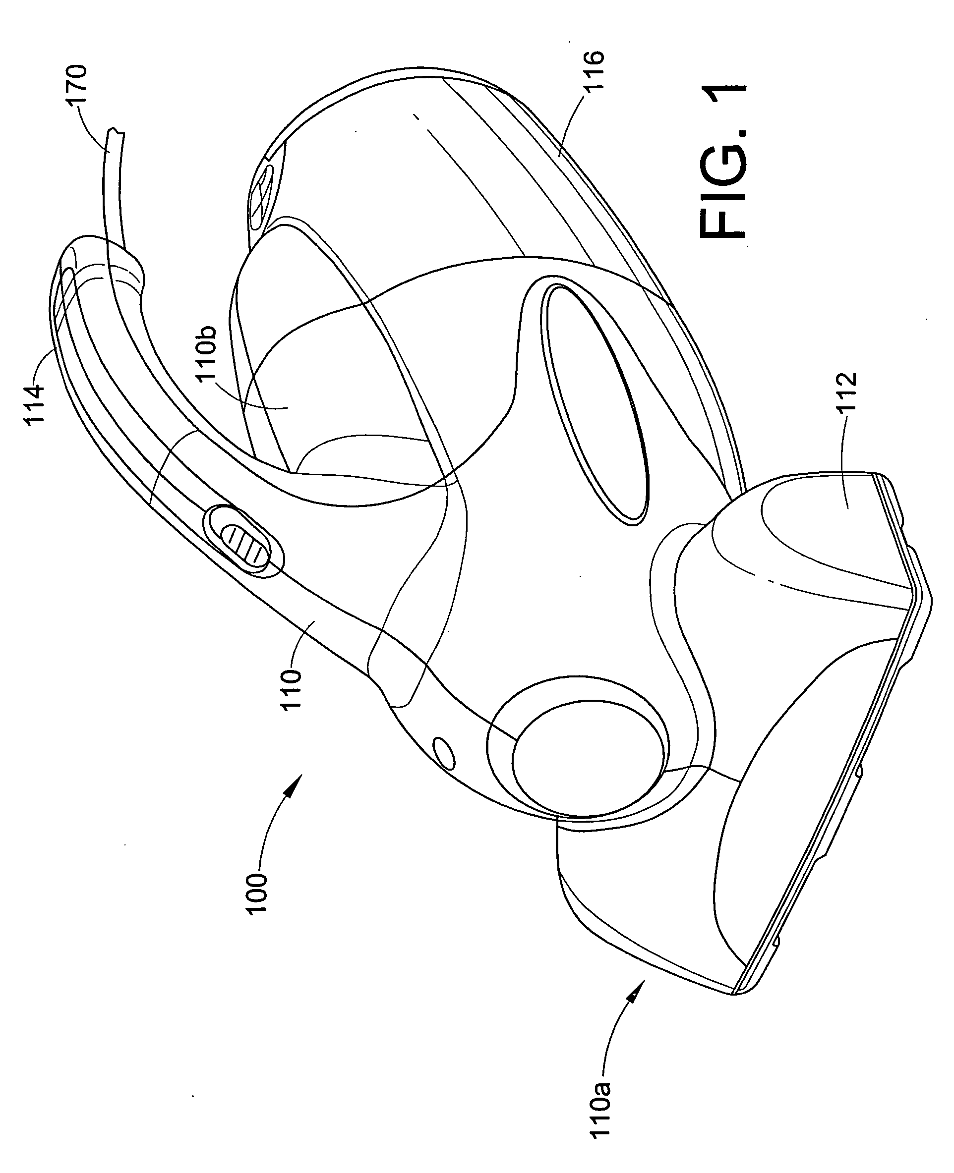
[0024] With reference to FIG. 1, a first embodiment of a hand-held vacuum cleaner 100 is shown. The hand-held vacuum cleaner 100 generally includes a housing 110, a suction nozzle 112, a handle 114, a dirt cup 116 and a suction fan and motor assembly 118 (FIG. 8). As shown in FIG. 1, the housing 110 can be formed of two bilaterally symmetrical pieces, a left half portion and a right half portion. Of course, other housing constructions are also contemplated. As can be seen in FIG. 9, the suction fan and motor assembly 118 is disposed internally to the housing 110. The suction nozzle 112 can be disposed adjacent a first end 110a of the housing 110, whereas the dirt cup 116 can be disposed adjacent a second end 110b of the housing 110.

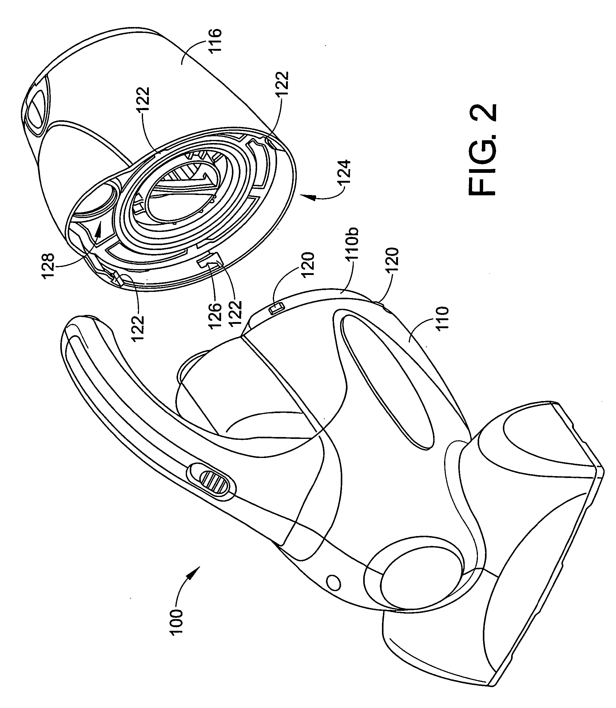
[0025] Now with reference to FIG. 2, a perspective view of the first embodiment 100 of the hand-held vacuum cleaner is shown with the dirt cup 116 removed from the housing 110. A plurality of nubs 120 are disposed along the second end 110b of the housing...


PUM


Abstract

The present invention relates to a vacuum cleaner. In one embodiment, a hand-held vacuum cleaner includes a housing having a first end and a second end, a suction nozzle located at the first end of the housing, and a suction fan and motor assembly located in the housing. A brushroll may be disposed within the suction nozzle. The hand-held vacuum cleaner further includes a dirt cup including an inlet, an outlet, a cyclonic flow chamber, a filter assembly, and a dirt cup door. The dirt cup is rotatably detachable from the housing. At least one nub cooperates with the at least one slot in the dirt cup to rotatably secure the dirt cup to the second end of the housing. In addition, the filter assembly includes at twist on filter cartridge.

Description

[0001] This application is a continuation-in-part of application Ser. No. 29 / 221,441, filed on Jan. 14, 2005, and Ser. No. 29 / 221,442, filed on Jan. 14, 2005, and Ser. No. 29 / 237,958, filed on Sep. 8, 2005.BACKGROUND [0002] The present invention relates to the field of vacuum cleaners. It finds particular application in conjunction with vacuum cleaners which employ cyclonic separation. [0003] Vacuum cleaners have become extremely popular for cleaning a variety of surfaces in homes, offices, cars or the like. One well known type of vacuum cleaner is a portable hand-held unit. Such units are utilized typically for small clean-up jobs or for cleaning in hard-to-reach places. These portable vacuum cleaner units are relatively light-weight and have a handle in order to enable a user to readily employ them in places where canister, upright, or shop-type vacuum cleaners cannot be used or are inconvenient to use. [0004] However, the above mentioned hand-held vacuum cleaners suffer a number ...

Claims


Application Information

Patent Timeline
Patent Type & Authority Applications(United States)
IPC IPC(8): A47L5/24A47L5/28
CPCA47L5/24A47L5/26A47L9/127A47L9/165A47L9/1666
Inventor KHALIL, DAVID
Owner ROYAL APPLIANCE MFG
Why Eureka
Try Eureka