Scanner and method for operating a scanner

Active Publication Date: 2006-07-20
FRAUNHOFER GESELLSCHAFT ZUR FOERDERUNG DER ANGEWANDTEN FORSCHUNG EV
View PDF10 Cites 21 Cited by
  • Summary
  • Abstract
  • Description
  • Claims
  • Application Information

AI Technical Summary

Benefits of technology

[0049] Advantageously, the surface relief of an object can be detected through knowing the position of the reflection of the light point on the surface relief and information on a position of the light beam in the illumination line, and at the same time this detection of the surface relief may be executed in an area-saving, cheap and mechanically robust way. The inventive approach may be realized in an area-saving way particularly because area cameras or line cameras need no longer be used, but a very compact setup of the collector is possible through the collector mirror stimulatable to oscillate in connection with the point-shaped light detector. Another advantage of the inventive approach is tha

Problems solved by technology

This one-dimensional detection of a position of a light beam only offers a coarse and delayed possibility for a determination of the position of the light beam, as the described method requires a complete pass of the light beam between two oscillation amplitude maxima of a travel path of the light beam.
However, all these prior-art approaches are of disadvantage in that they require either an area camera or at least a line camera for detecting the image reflected by the object

Method used


Image

  • Scanner and method for operating a scanner
  • Scanner and method for operating a scanner
  • Scanner and method for operating a scanner

Examples


Example

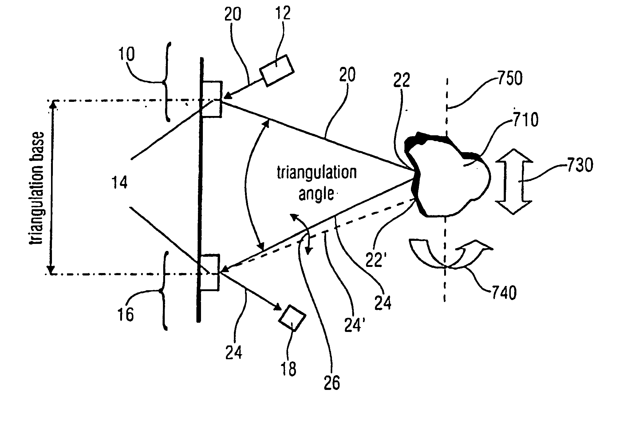
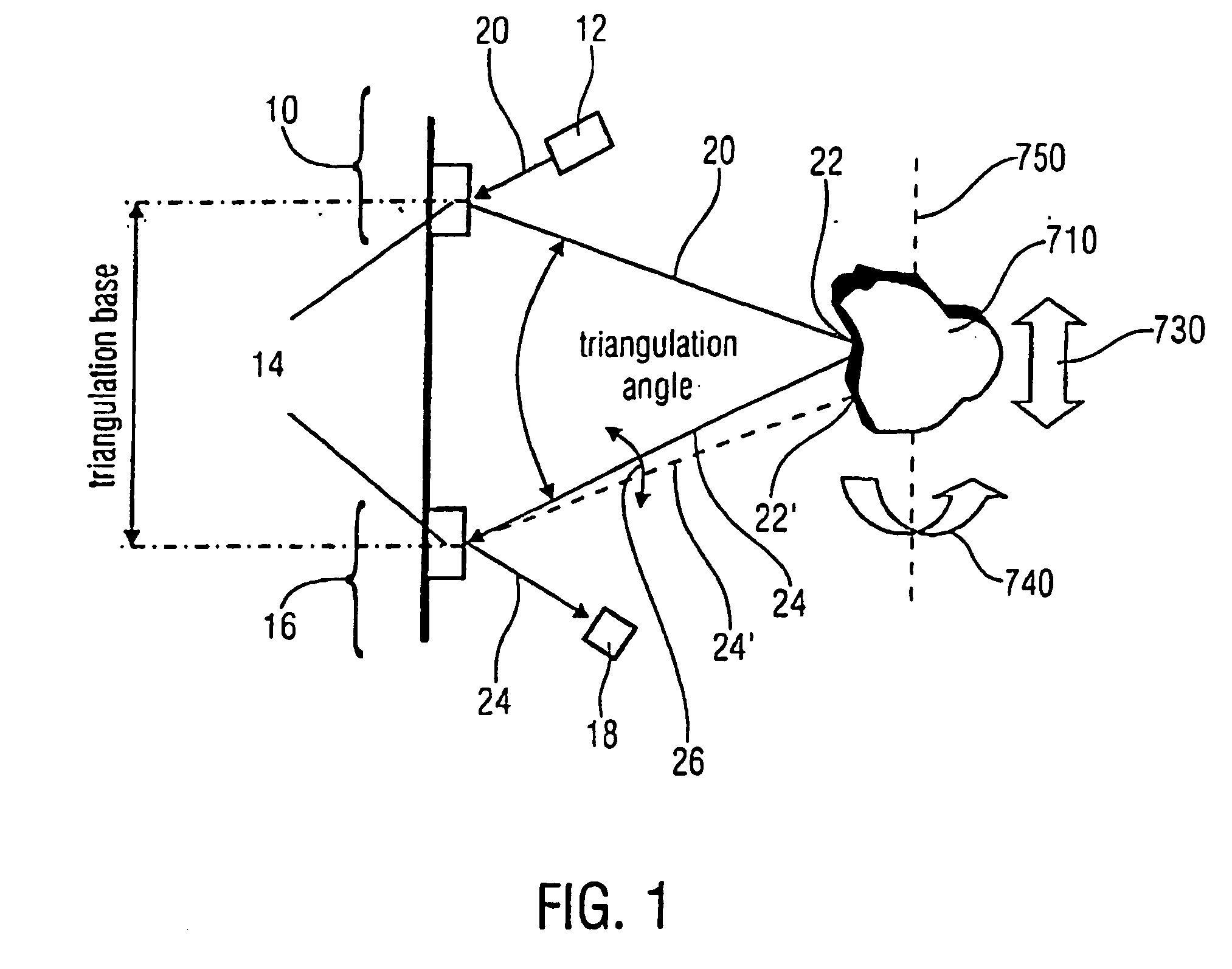
[0062] The first embodiment of the inventive scanner is schematically illustrated in FIG. 1. Here, FIG. 1 includes a projector 10 having a light source 12 and a projector micro scanner mirror 14 and a collector 16 having a collector micro mirror 14 and a photo-sensor 18. The two micro mirrors 14 of the projector 10 and the collector 16 are thus arranged at a distance from each other that serves as a triangulation basis. Via the light source 12, which is preferably a point-shaped light source, a light beam is directed to the micro mirror 14 of the projector 10, wherein the same reflects the light beam 20 to the object 710, whereby the light point or the illuminated location 22, respectively, results. The illuminated location 22 now forms a reflection 24 which is mapped from the micro mirror 14 of the collector 16 on the preferably point-shaped light detector 18, which may for example be a photo diode. Accordingly, the light source 12 may be an LED (LED=Light Emitting Diode) or a lase...


PUM


Abstract

A scanner for providing a possibility of detecting a surface relief of an object includes a projector configured to guide a light beam in an illumination line over the surface relief to obtain an illuminated location on the surface relief, the projector being further configured to output a projection signal from which a position of the light beam in the illumination line is derivable. Additionally, the scanner includes a collector having a collector micro mirror stimulatable to oscillate in two dimensions and a point-shaped light detector, the collector micro mirror being oscillatingly arranged in a first direction of the illumination line and in a second direction differing from the first direction such that a reflection of the illuminated location within a scan area of the micro scanner mirror is imagable by it onto the point-shaped light detector, and the collector being configured to output a detection signal from which a position of the illuminated location in the first and second directions is derivable.

Description

CROSS-REFERENCE TO RELATED APPLICATION [0001] This application claims priority from German Patent Application No. 10 2005 002 190.5, which was filed on Jan. 17, 2005, and is incorporated herein by reference in its entirety. BACKGROUND OF THE INVENTION [0002] 1. Field of the Invention [0003] The present invention relates to the technical field of contactless detection or measurement, respectively, of three-dimensional objects. In particular, the present invention relates to the technical sub-field of scanners for detecting a surface relief by means of optical scanning. [0004] 2. Description of Prior Art [0005] Known scanners for short object distances mainly use the method of triangulation, as it is illustrated in FIG. 7. Here, from a light source 705 of a scanner 700 a suitable light pattern is protected onto the object 710 to be examined, while an electronic image receiver 720 detects the resulting image from a different angle of view. As it is illustrated in FIG. 7, the surface pr...

Claims


Application Information

Patent Timeline
IPC IPC(8): G01B11/24
CPCG01B11/24
Inventor SCHELINSKI, UWESCHOLLES, MICHAELWOLTER, ALEXANDER
Owner FRAUNHOFER GESELLSCHAFT ZUR FOERDERUNG DER ANGEWANDTEN FORSCHUNG EV
Why Eureka
Try Eureka