Computer peripheral device mounting arrangement with two locking elements

a technology for computer peripheral devices and mounting arrangements, which is applied in the direction of electrical apparatus construction details, electrical apparatus casings/cabinets/drawers, instruments, etc., can solve the problems of insufficient support for inability to meet the shock and vibration requirements of many computer peripheral devices, and inability to access screws only from the sides of the computer peripheral devices. , to achieve the effect of reducing the number of computer peripheral devices, reducing the number of components, and reducing the number of parts

Inactive Publication Date: 2006-07-20
QUANTUM CORP
View PDF6 Cites 13 Cited by
  • Summary
  • Abstract
  • Description
  • Claims
  • Application Information

AI Technical Summary

Benefits of technology

[0006] There is a need for a computer peripheral device mounting arrangement that overcomes the concerns raised by prior mounting arrangements and allows a drive to be mounted from the top and / or the front, requires very minimal disassembly, is compatible with standard half high devices, is easily manufacturable and low cost, readily assembled, meets computer peripheral device shock and vibration requirements, and uses a minimal number of screws.
[0008] The mounting arrangement of the present invention thus provides for configuration that allows the computer peripheral device to be non-lockingly secured and then locked with only a single locking element, such as a screw, at each computer peripheral device mount. The arrangement thus satisfies all the needs without requiring more than a single locking element for each computer peripheral device mount of a pair of computer peripheral device mounts. This reduces installation costs while still providing secure mounting of the computer peripheral device within a drive bay.

Problems solved by technology

The mounting of computer peripherals, such as computer peripheral devices, into a rack mount enclosure or other structure, typically poses a number of challenges.
A four screw mounting solution in a typical mounting configuration creates problems in that the screws can only be accessed from the sides of the computer peripheral device and requires special tooling and / or processes.
The special tooling and / or processes are not only costly but can be prohibitive in field repair of the unit.
Another problem with the four screw mounting arrangement is that it does not provide enough support to meet shock and vibration requirements of many computer peripheral devices, such as typical tape drives.
Increasing the number of screws to six screws resolves many of these concerns but adds increased costs due to the additional tooling and hardware required.
Hence, in practice, a six screw mounting solution is not desirable.

Method used


Image

  • Computer peripheral device mounting arrangement with two locking elements
  • Computer peripheral device mounting arrangement with two locking elements
  • Computer peripheral device mounting arrangement with two locking elements

Examples


Embodiment Construction

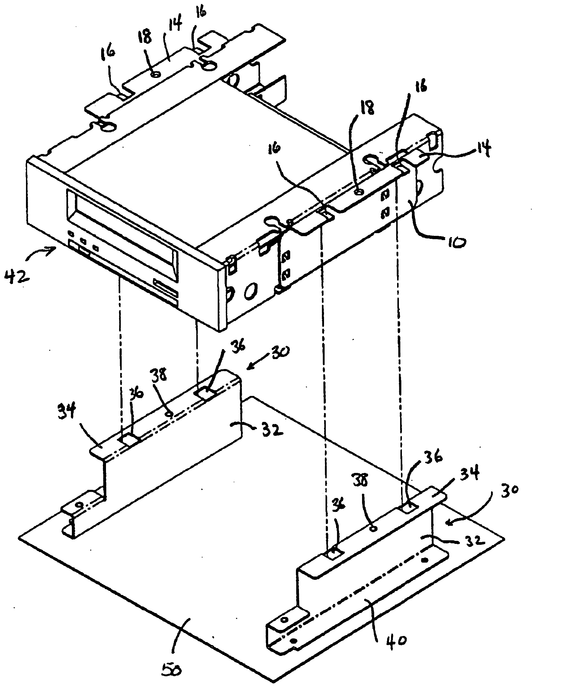
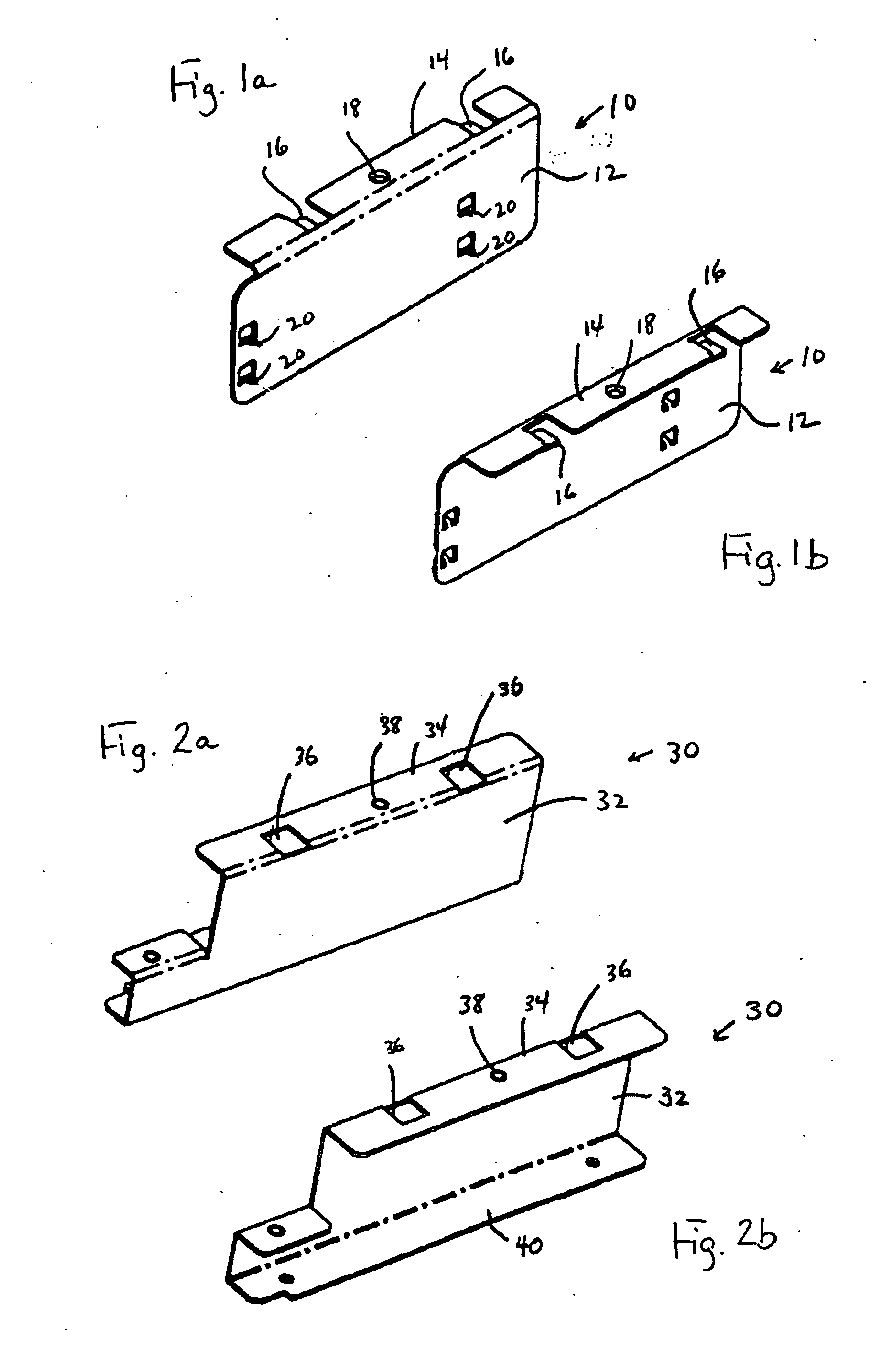
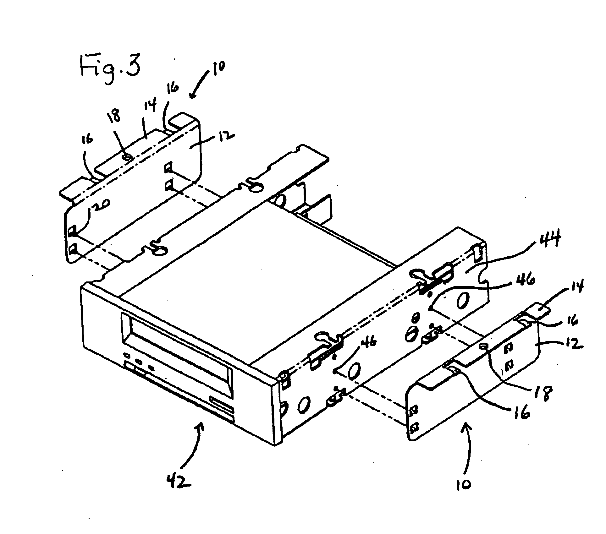
[0018] The present invention addresses and solves problems related to the mounting of computer peripheral devices within the drive bay of an enclosure, and more particularly, to the securing of the computer peripheral device in a manner that meets computer peripheral device shock and vibration requirements but employs relatively few screws. The present invention achieves this, in part, by providing a computer peripheral device mounting arrangement employing a pair of computer peripheral device mounts. Each computer peripheral device mount includes a computer peripheral device side bracket that is mounted to an exterior side wall of the computer peripheral device, and a drive bay bracket that is provided in a drive bay. A non-locking securement arrangement is provided on the computer peripheral device side bracket and the drive bay bracket. This arrangement non-lockingly secures the computer peripheral device side bracket to the drive bay bracket. Once held in place by the non-lockin...


PUM


Abstract

A computer peripheral device mounting arrangement has a pair of computer peripheral device mounts. Each computer peripheral device mount includes a computer peripheral device side bracket that is mounted on an exterior sidewall of the computer peripheral device. Each computer peripheral device mount also includes a drive bay bracket fixedly positioned in a drive bay. Clips and slots provide a non-locking securement arrangement on the computer peripheral device side bracket and the drive bay bracket. The computer peripheral device side bracket and the drive bay bracket of each computer peripheral device mount is secured by a single screw that prevents relative movement between the computer peripheral device side bracket and the drive bay bracket.

Description

RELATED APPLICATIONS [0001] This application claims priority to provisional application 60 / 483,568, filed on Jun. 26, 2003, which is incorporated by reference in its entirety.FIELD OF THE INVENTION [0002] The present invention relates to the field of computer peripheral devices, and more particularly, to the mounting of computer peripheral devices within a drive bay. BACKGROUND OF THE INVENTION [0003] The mounting of computer peripherals, such as computer peripheral devices, into a rack mount enclosure or other structure, typically poses a number of challenges. For example, a typical mounting configuration requires the use of four to six screws. A four screw mounting solution in a typical mounting configuration creates problems in that the screws can only be accessed from the sides of the computer peripheral device and requires special tooling and / or processes. The special tooling and / or processes are not only costly but can be prohibitive in field repair of the unit. Another proble...

Claims


Application Information

Patent Timeline
Patent Type & Authority Applications(United States)
IPC IPC(8): G06F1/16H05K7/16G06F1/18
CPCG06F1/184G06F1/187
Inventor GREEN, DOUGLAS A.HANSON, SCOTT L.THOMPSON, MARK R.
Owner QUANTUM CORP
Why Eureka
Try Eureka