
Folding high voltage electric power switch

a high-voltage electric power switch and folding technology, which is applied in the field of electric switchgear, can solve the problems of difficult assembly, adjustment and testing of the switch in the field, and the large size of the high-voltage transmission switch (e.g. above 25 kv) to be transported on a road truck when fully assembled, and achieves the effects of easy folding for transportation, simple unfolding, and minimal disassembly

Active Publication Date: 2013-09-24
SOUTHERN STATES
View PDF4 Cites 2 Cited by
  • Summary
  • Abstract
  • Description
  • Claims
  • Application Information

AI Technical Summary

Benefits of technology

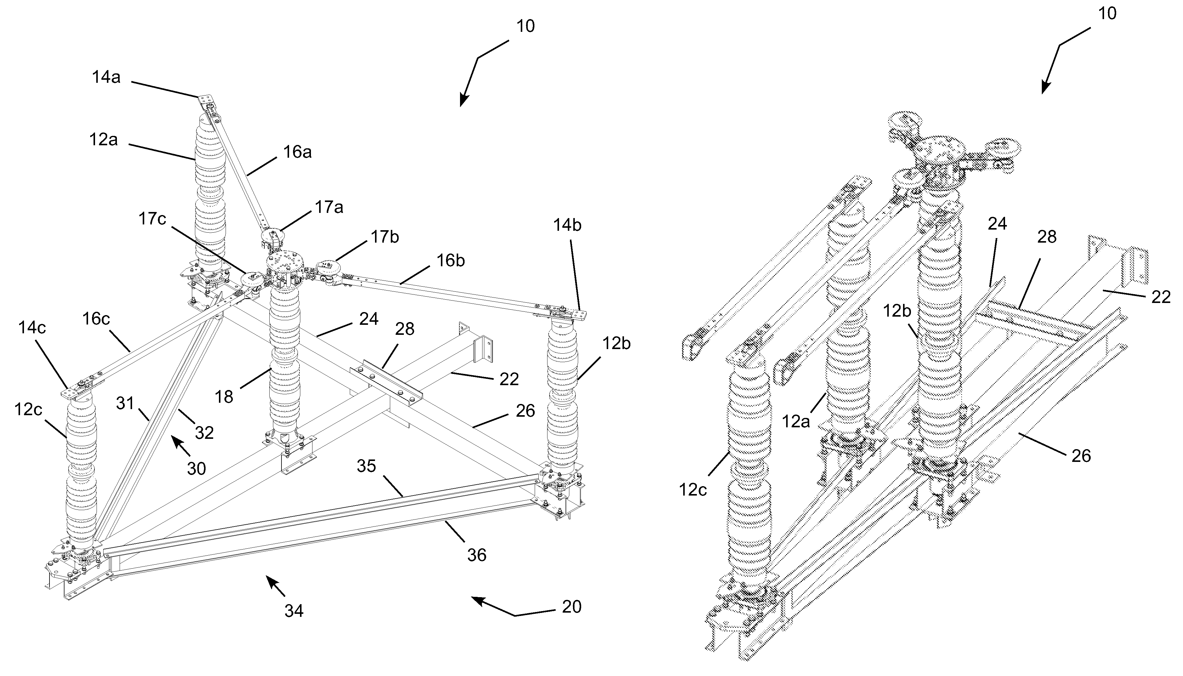
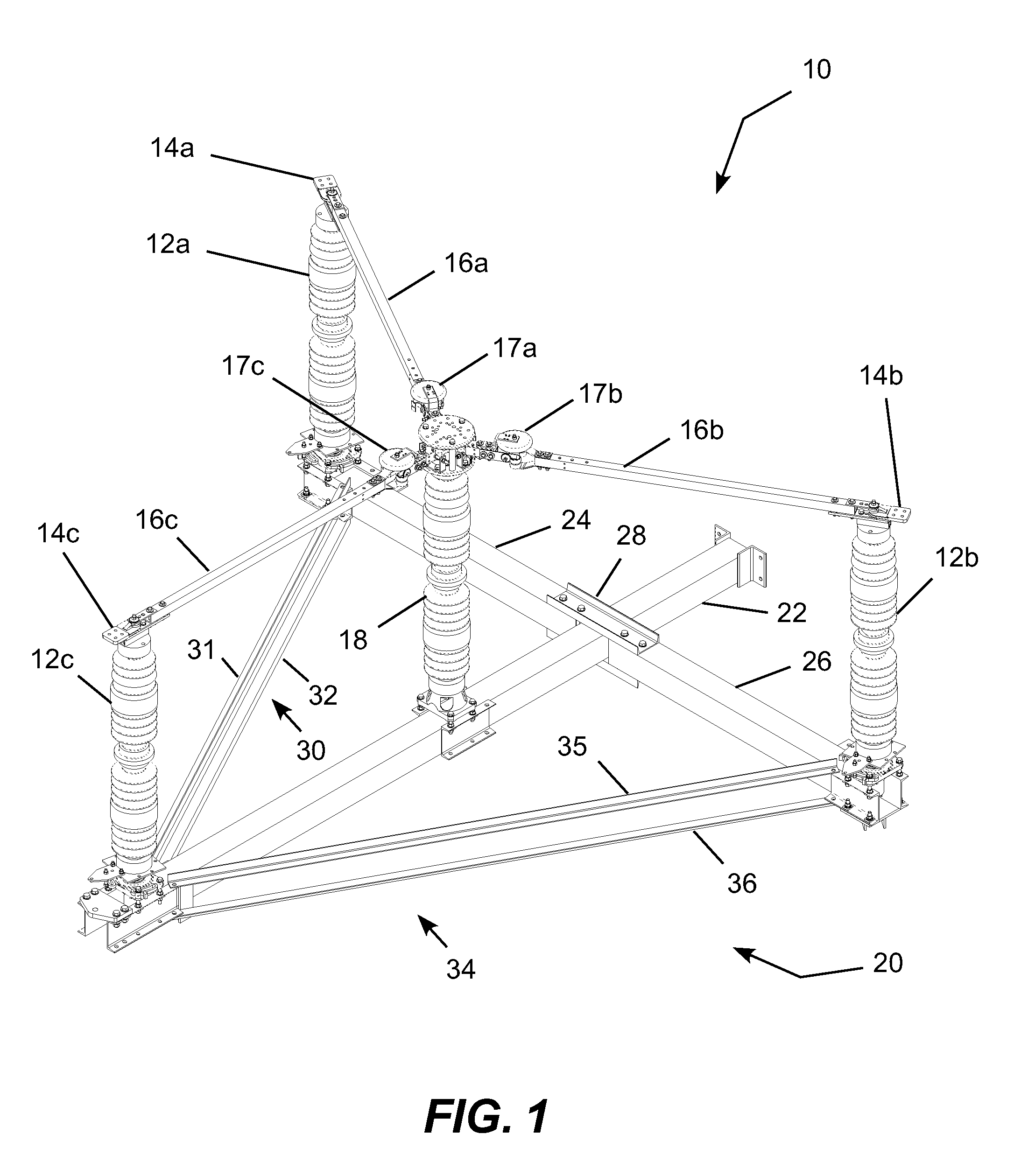
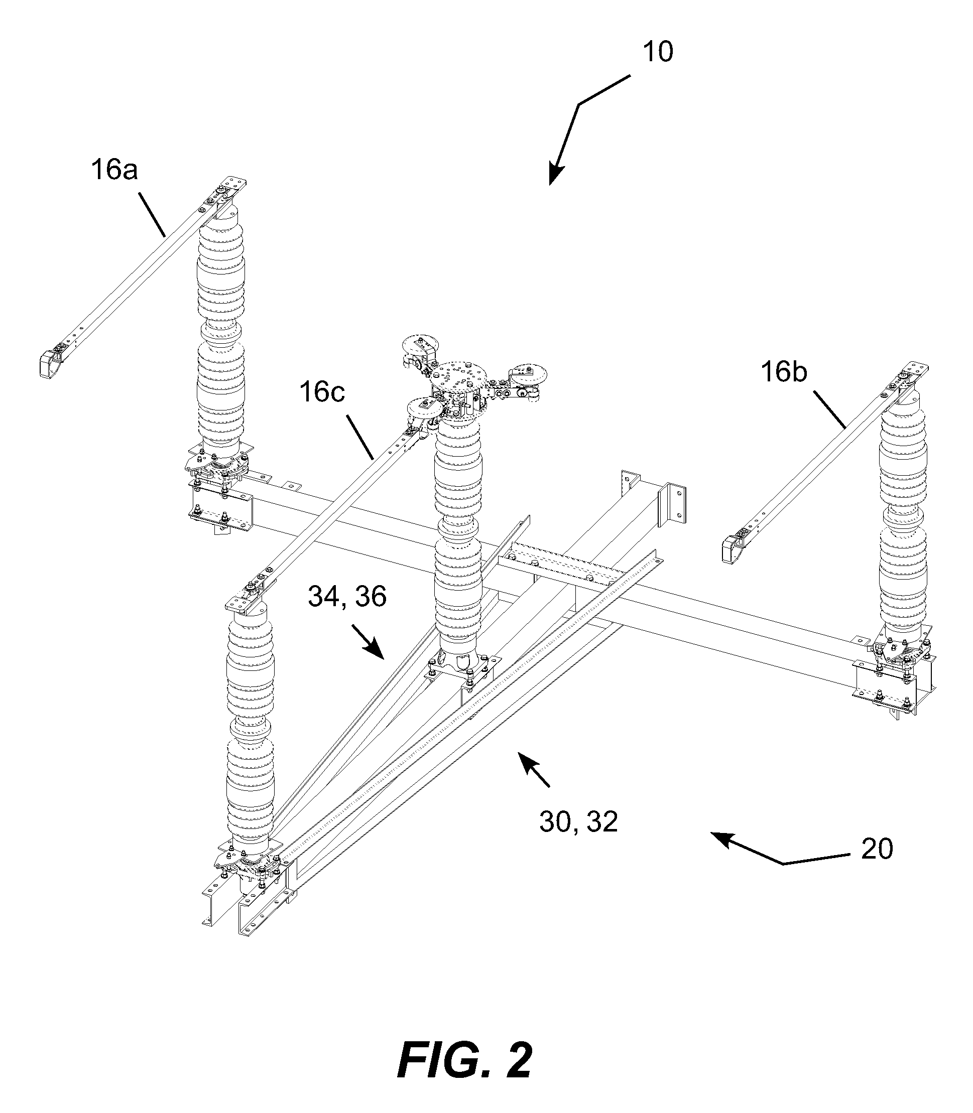
This patent describes a folding high voltage electric power switch that can be assembled, adjusted and tested at the factory and then folded for shipping on a road truck with minimal disassembly. The switch includes a platform with structural beams and struts that easily fold for transportation and unfold for installation in the field while the beams, struts, insulators, and blade arms remain attached together. This allows for complete assembly, testing, and adjustment of the switch at the factory while limiting the field assembly to simple unfolding and securing together the structural components of the switch platform. The technical effect of this invention is a modular and easy-to-assemble, adjust, and test folding high voltage electric power switch that can be easily transported and installed in the field.

Problems solved by technology

While switches generally rated for sub-transmission voltages (e.g., approximately 25 kV and below) are physically small enough to be assembled at a factory and transported on a road truck fully assembled, higher voltage transmission switches (e.g., above 25 kV) are generally too large to be transported on a road truck when fully assembled.
As electric power lines run in all types of terrain, assembly, adjustment and testing of the switch in the field can be difficult.
Although assembly, adjustment and testing in the factory would be preferable, this approach has not been available for higher voltage transmission switches.

Method used


Image

  • Folding high voltage electric power switch
  • Folding high voltage electric power switch
  • Folding high voltage electric power switch

Examples


Embodiment Construction

[0016]The present invention may be embodied in a folding high voltage electric power switch that can be fully assembled, tested and adjusted in the factory and then folded for shipping on a road truck with minimal disassembly. The platform includes structural beams and struts that easily fold for transportation and unfold for installation in the field with minimal field assembly largely limited to folding out and securing of support beams and struts.

[0017]More specifically, the foldable switch includes a number of phase insulators (e.g., two phase insulators for a 2-way switch and three phase insulators for a three-way switch), a central switch insulator and a number of blade arms, each selectively connecting an electric power tap at the central insulator to an electric power tap at a respective phase insulator. The platform that supports the insulators folds with the insulators, power taps, blade arms, structural beams and struts of the platform remaining attached to each other for...


PUM


Abstract

A folding high voltage electric power switch that can be fully assembled, tested and adjusted at the factory and then folded for shipping on a road truck with minimal disassembly. The switch can then be readied for installation with minimal field assembly largely limited to unfolding and securing support beams and struts. The switch includes a number of phase insulators (i.e., two phase insulators for a 2-way switch and three phase insulators for a three-way switch), a central switch insulator and a number of blade arms, each selectively connecting an electric power tap at the central insulator to an electric power tap at a respective phase insulator. The platform includes structural beams and struts that easily fold for transportation and unfold for installation in the field while the beams, struts, insulators and blade arms remain attached together.

Description

TECHNICAL FIELD[0001]The present invention relates to electric switchgear and, more particularly, relates to folding high voltage electric power switch that allows assembly, testing and adjustment of all major components at the factory, folding of the switch for transportation, and minimal assembly in the field largely limited to folding out and securing supports beams and struts with a small number of bolts.BACKGROUND OF THE INVENTION[0002]High voltage electric power line switches are used for a variety of purposes, such as interrupting current to loads and other circuit devices. Higher voltage switches are physically larger than lower voltage switches due to the required insulating distances. While switches generally rated for sub-transmission voltages (e.g., approximately 25 kV and below) are physically small enough to be assembled at a factory and transported on a road truck fully assembled, higher voltage transmission switches (e.g., above 25 kV) are generally too large to be t...

Claims


Application Information

Patent Timeline
Patent Type & Authority Patents(United States)
IPC IPC(8): H01H31/02
CPCH01H31/20H01H31/02H01H9/08
Inventor BLALOCK, FRANK CLAY
Owner SOUTHERN STATES
Learn More