Single-axis fin deployment system

a deployment system and single-axis technology, applied in the field of single-axis fin deployment systems, can solve the problems of reducing the likelihood of damage to the fin, various relatively complex deployment systems, complex and expensive design, construction and maintenance,

Active Publication Date: 2006-07-27
RAYTHEON CO
View PDF33 Cites 31 Cited by
  • Summary
  • Abstract
  • Description
  • Claims
  • Application Information

AI Technical Summary

Benefits of technology

[0009] There is a need for a simple and reliable system to stow stowable vehicle fins in a stowed configuration, deploy the fins about a single axis, and retain or lock the stowable vehicle fins into a deployed configuration and, in some cases, control the fins in the deployed configuration. The present invention provides a deployment system for stowing and deploying stowable fins that meets this need and provides further advantages in cost, weight and space savings. Additionally, the present invention allows for smaller vehicles with increased capability and performance.

Problems solved by technology

Stowing fins in such a manner also reduces the likelihood of damage to the fins during storage and handling.
Various relatively complex deployment systems have been developed to permit the fins to be stowed, deployed and locked into place.
The systems presently used to retain, deploy, lock into place and control (if applicable) the fins tend to be relatively heavy, complex and expensive to design, build and maintain.
Moreover, some systems occupy a relatively large volume within the missile, a significant disadvantage because of the limited space within the missile.

Method used


Image

  • Single-axis fin deployment system
  • Single-axis fin deployment system
  • Single-axis fin deployment system

Examples


Embodiment Construction

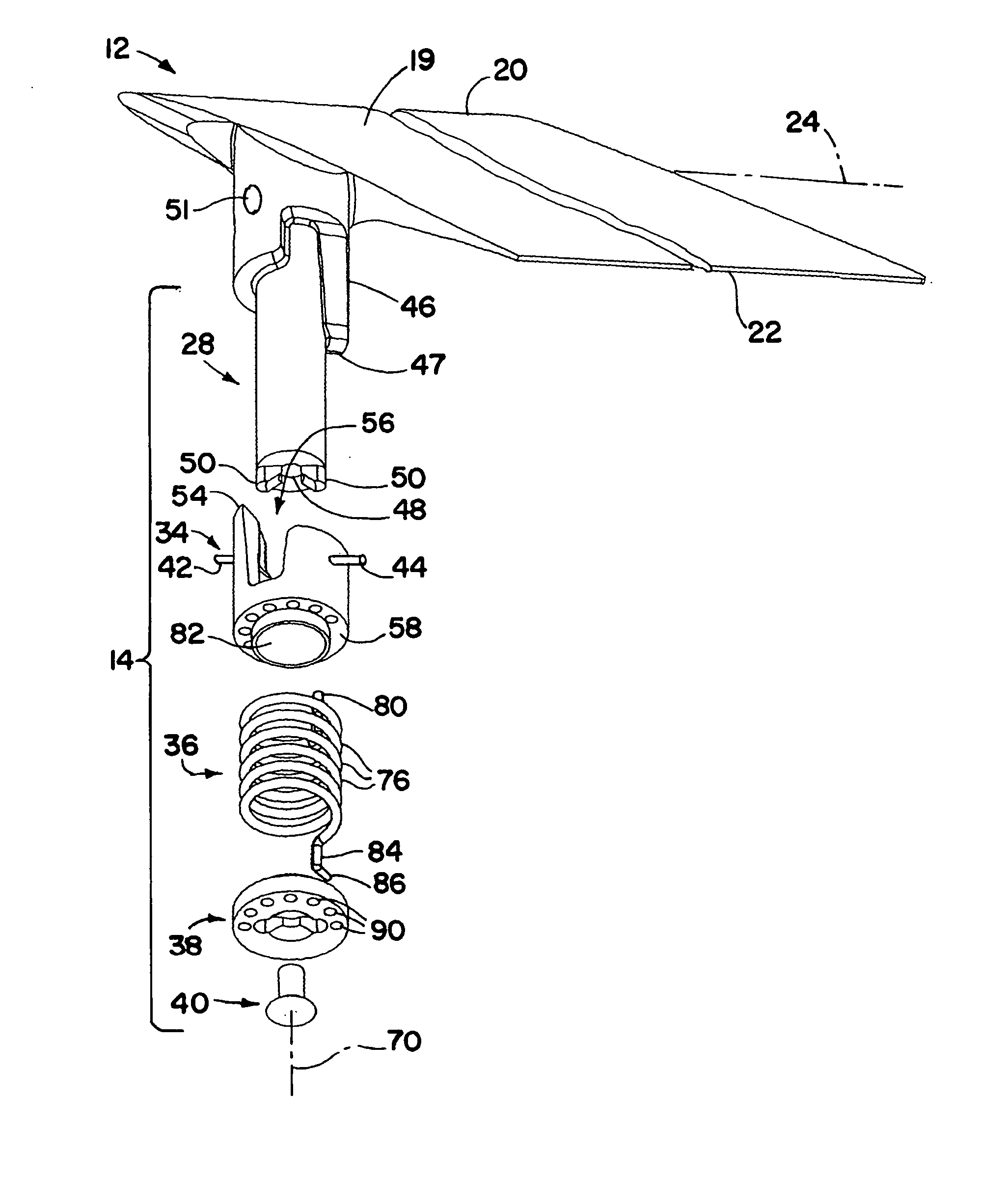
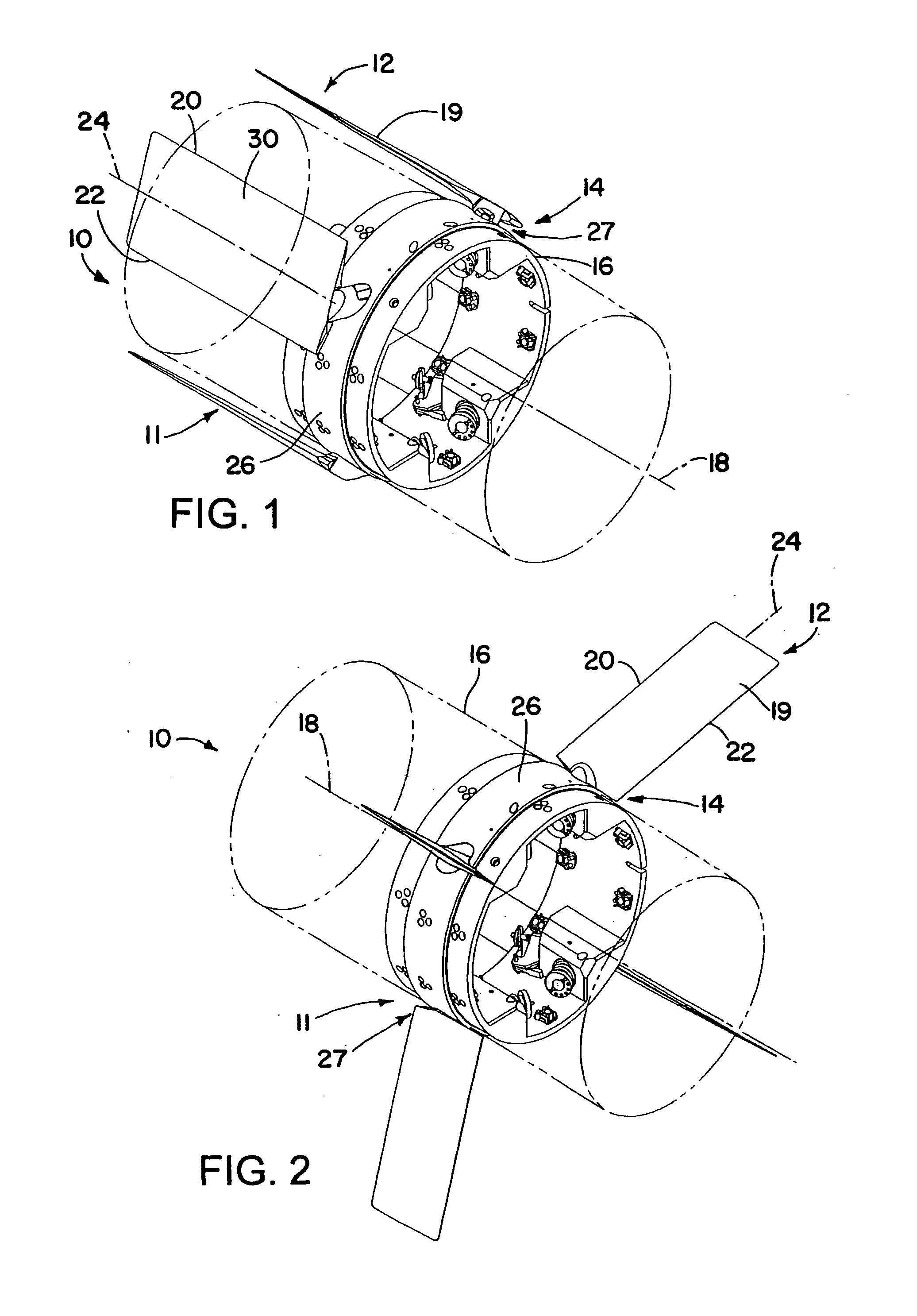
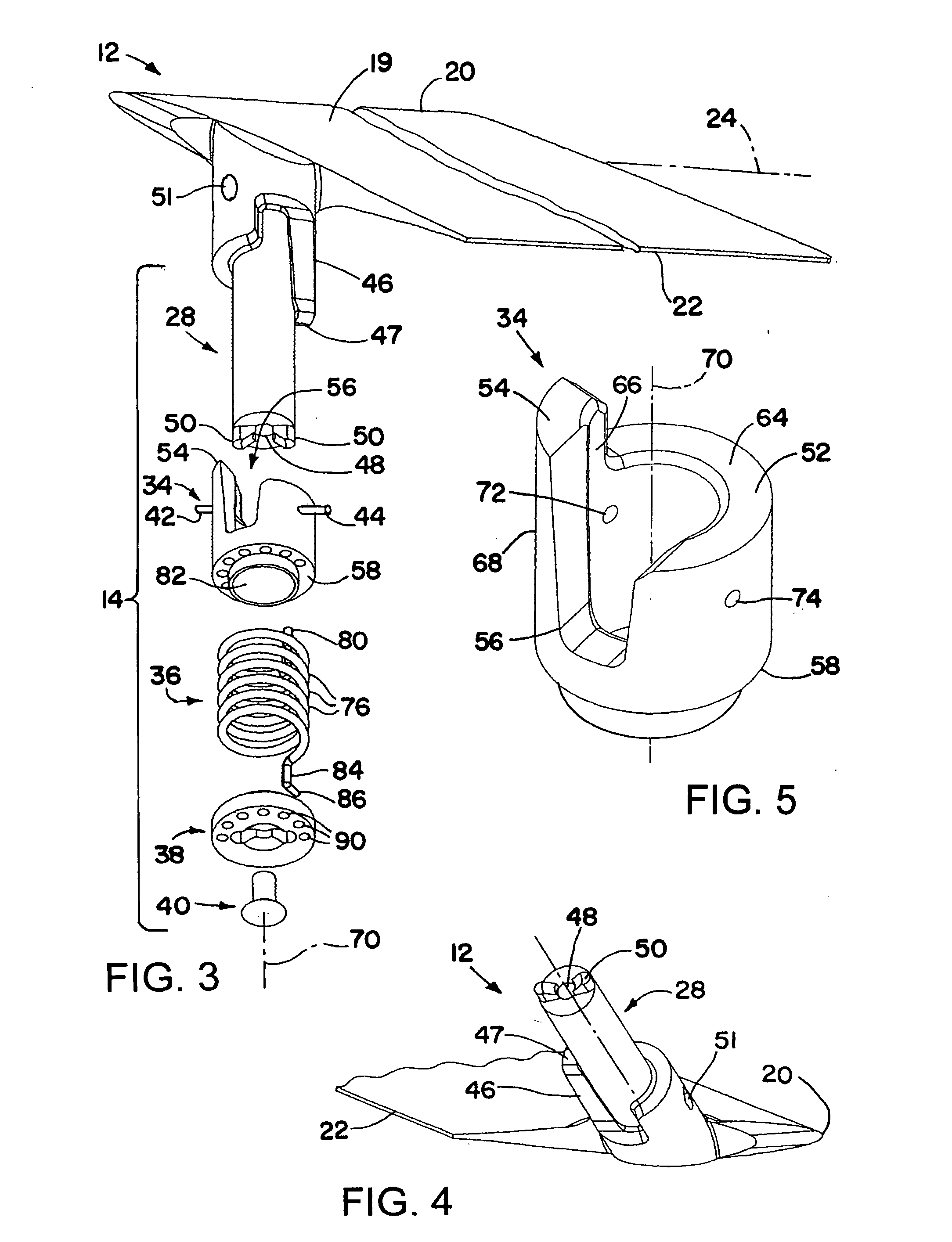
[0025] A missile has fins that rotate about a single axis to deploy from a stowed position, in which a foil of the missile may be substantially parallel to a missile body, to a deployed position, in which the foil may be substantially perpendicular to the missile body. A foil longitudinal axis of each fin is angled relative to a shaft of the fin, such that a single-axis rotation of the shaft moves the wing or foil from the stowed position to a deployed position. A coil spring may provide both torsion and compression forces to rotate the fin into the deployed position and lock it into place. Torsion rotates the shaft until it reaches a seat on a bushing that is around the shaft. Then compression forces from the spring engage a keyed protrusion on the shaft with a corresponding keyway in the bushing, locking the shaft in place. There may be an additional lock once the fin is deployed, such as a spring-loaded pin in the missile body that engages a depression in the shaft.

[0026] Referr...


PUM


Abstract

A missile has fins that rotate about a single axis to deploy from a stowed position to a deployed position. A foil longitudinal axis of each fin is angled relative to a shaft of the fin, such that a single-axis rotation of the shaft moves the foil from the stowed position to a deployed position. A coil spring may provide both torsion and compression forces to rotate the fin into the deployed position and lock it into place. Torsion rotates the shaft until it reaches a seat on a bushing that is around the shaft. Then compression forces from the spring engage a keyed protrusion on the shaft with a corresponding keyway in the bushing, locking the shaft in place. There may be an additional lock once the fin is deployed, such as a spring-loaded pin in the missile body that engages a depression in the shaft.

Description

FIELD OF THE INVENTION [0001] The present invention generally relates to vehicles having stowable fins, and, more particularly, to a system for stowing and deploying the fins. BACKGROUND OF THE INVENTION [0002] Many types of vehicles utilize two or more protruding surfaces to affect the fluid flow around the vehicle, thereby facilitating control of its flight path. Exemplary types of such vehicles include aircraft, airships, unmanned aerial vehicles, and various types of ordnance, e.g., missiles, rockets, guided projectiles, bombs, torpedoes and the like. [0003] For example, missiles generally have a cylindrical body, with at least two aerodynamic surfaces or fins that extend outwardly from the sides of the missile body (vehicle housing) to affect the aerodynamic characteristics of the missile in flight. The fins typically have an airfoil shape that is oriented edge-on or slightly inclined relative to the airflow when the missile is flying in a straight line. These fins may be, for ...

Claims


Application Information

Patent Timeline
Patent Type & Authority Applications(United States)
IPC IPC(8): F42B10/14
CPCF42B10/14
Inventor PARINE, JOHN C.KOESSLER, JEFFREY H.GOGINENI, PURNACHANDRA R.PEREZ, JUAN A.KEBSCHULL, MARTIN A.
Owner RAYTHEON CO
Why Eureka
Try Eureka