Method and apparatus for promoting the complete transfer of liquid drops from a nozzle

a technology of liquid drop and complete transfer, which is applied in the direction of printing, etc., can solve the problems of large-scale production, large-scale production, and high manufacturing cost, and achieve the effect of promoting the complete transfer of liquid drop from the nozzl

Active Publication Date: 2006-07-27
RGT UNIV OF CALIFORNIA
View PDF3 Cites 270 Cited by
  • Summary
  • Abstract
  • Description
  • Claims
  • Application Information

AI Technical Summary

Benefits of technology

[0015] In another embodiment, a method of transferring or printing liquid droplets to a surface includes the steps of providing a printhead for transferring liquid droplets to a surface. The printhead includes at least one nozzle having a substantially circular orifice having an inner circumferential surface, of which, at least a portion is serrated. A source of liquid is loaded into the printhead device, typically within a reservoir. Alternatively, the source of liquid may come from an external instrument that is coupled to the device via one or more connections. In still another example, the liquid reservoir may...

Problems solved by technology

These microarray devices, however, require the formation of high-density hybridization sites or spots on a solid surface.
While high-density test sites may be created using this method, there are significant manufacturing costs due to the use of light blocking masks and related lithographic equipment.
This process, while suitable for large-scale production, is simply too expensive for small or intermediate scale productions.
Unfortunately, after repeated use, the tip of the pin (which is typically stainless steel) tends to deform plastically, thereby resulting in test sites having inconsistent spot size and shapes.
While inkjet technology is mature and widely used in the case of traditional inkjet printers (used in the home and in business), the same technology cannot be directly translated into microarray applications.
For example in microa...

Method used


Image

  • Method and apparatus for promoting the complete transfer of liquid drops from a nozzle
  • Method and apparatus for promoting the complete transfer of liquid drops from a nozzle
  • Method and apparatus for promoting the complete transfer of liquid drops from a nozzle

Examples


Embodiment Construction

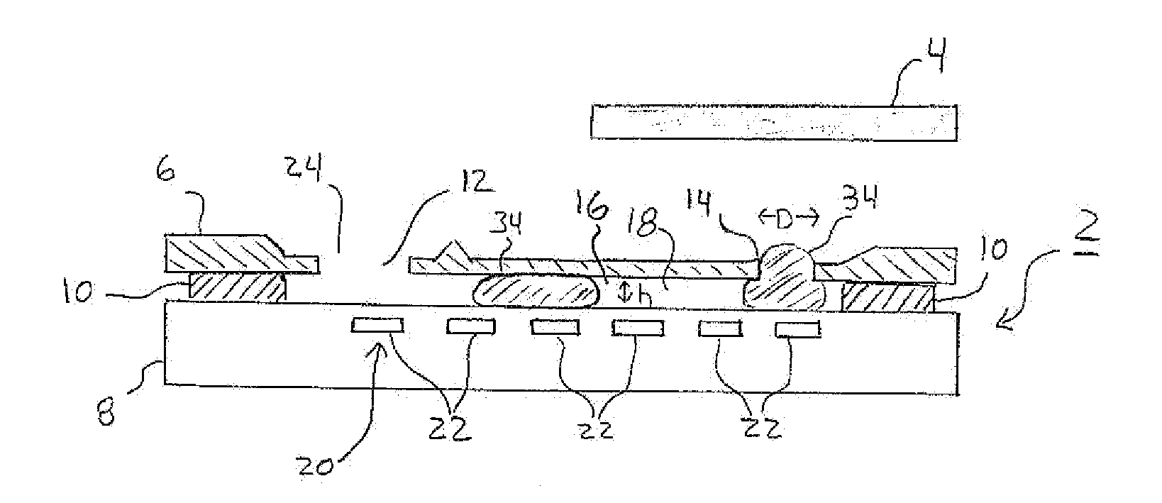
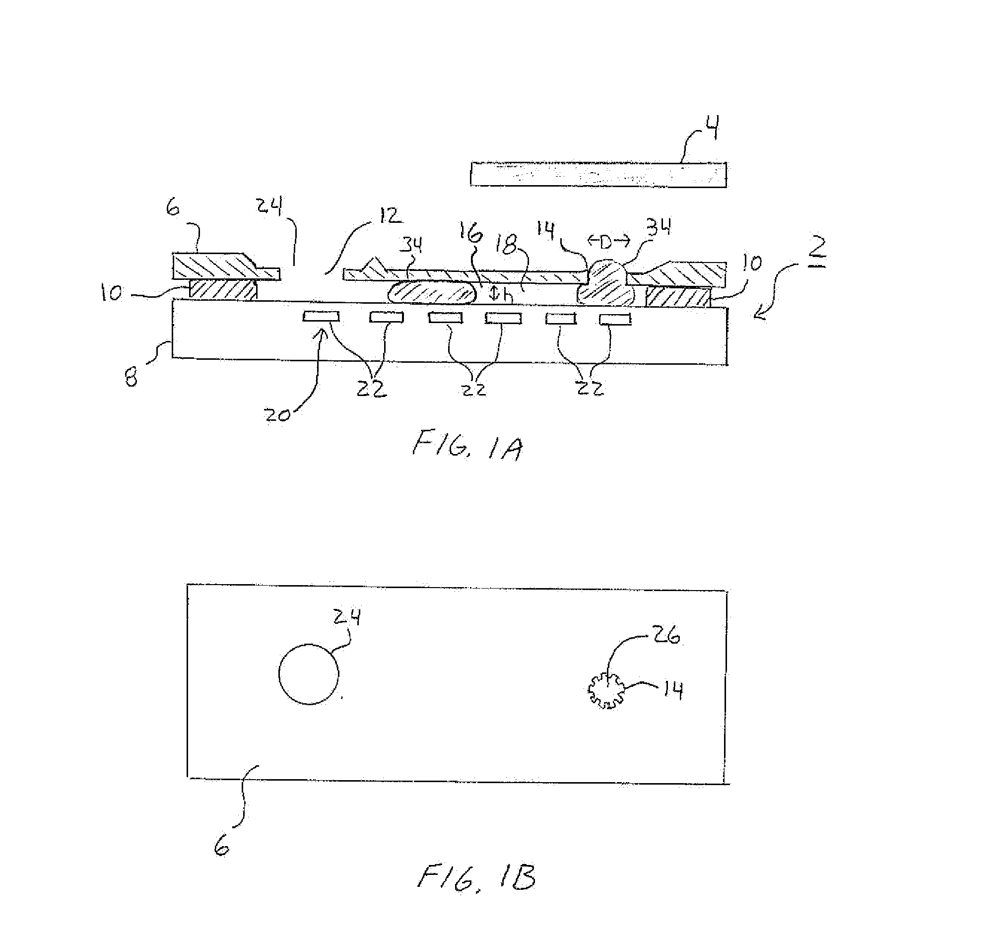
[0034]FIGS. 1A and 1B schematically illustrate a printhead device 2 for transferring liquid droplets 34 to a surface 4. In one embodiment, the printhead 2 is formed using an upper portion 6 and a lower portion 8 that are separated from one another via a spacer 10 or the like. The assembled printhead 2 includes a liquid source 12 that is fluidically connected to a nozzle 14. For instance, the liquid source 12 may be coupled to the nozzle 14 via a passageway 16, which in certain embodiments, may comprise a microfluidic channel 18. In certain embodiments, the liquid source 12 may comprise a reservoir. FIGS. 1A and 1B also illustrate a printing surface 4 in close proximity to the outlet of the nozzle 14. The printing surface 4 may be formed from a wetting (e.g., hydrophilic) substrate, for example, a glass plate or the like.

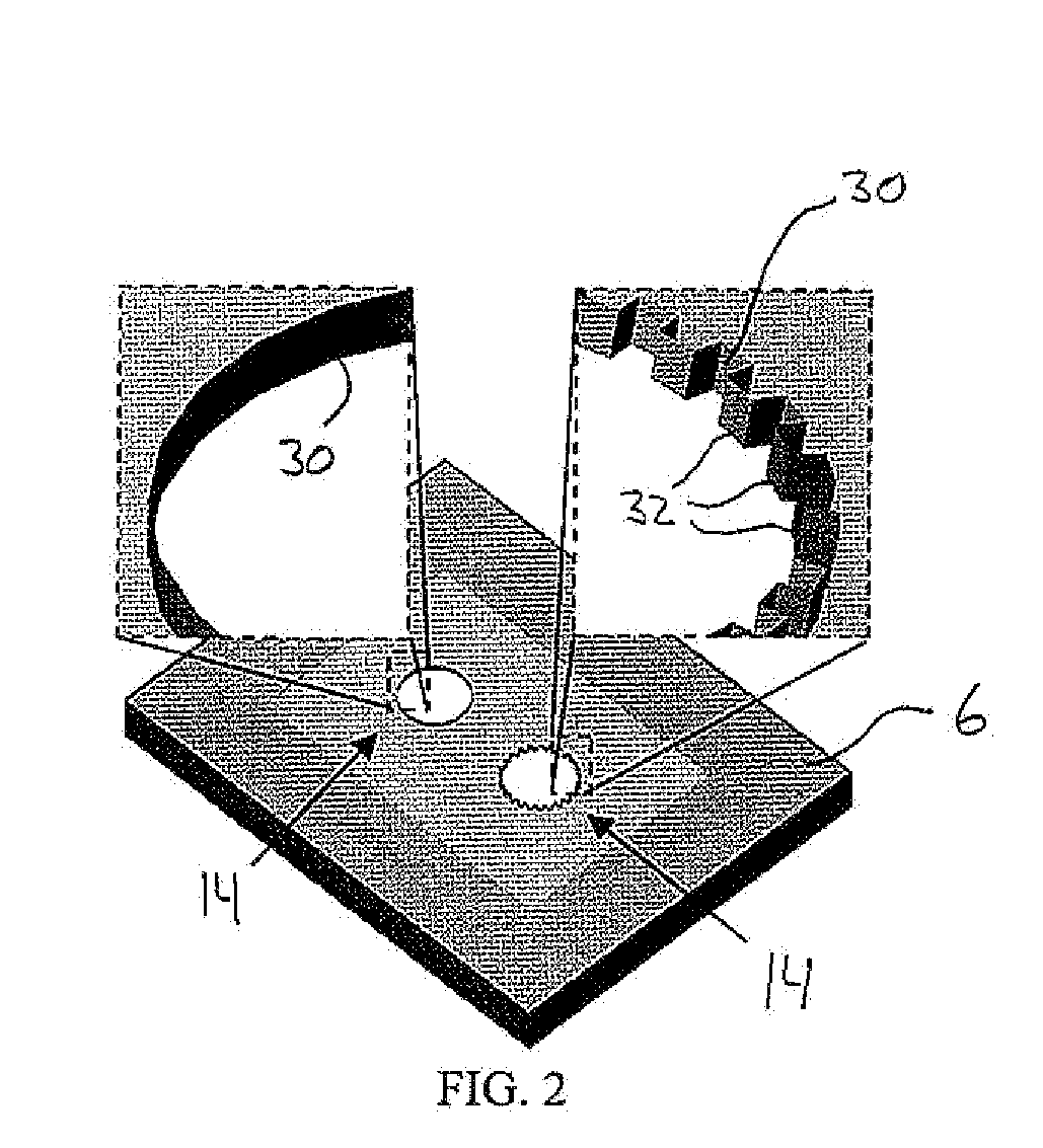
[0035] The upper portion 6 of the printhead 2 may be formed within a substrate such as a silicon wafer by using conventional semiconductor processing techniques. Fo...


PUM


Abstract

A printhead device for transferring liquid droplets from a nozzle includes a liquid source coupled to a nozzle via a microchannel. The nozzle is formed from an orifice having an inner circumferential surface, wherein at least a portion of the inner circumferential surface is serrated. Liquid droplets are transported from the source to the nozzle using a liquid droplet driver (e.g., employing a plurality of driving electrodes). Transfer of droplets to another surface can be accomplished by contacting a bulging droplet in the nozzle with a printing surface. The surface and/or nozzle are then moved relative to one another to effectuate complete transfer of the liquid drop from the nozzle.

Description

[0001] This Application claims priority to U.S. Provisional Patent Application No. 60 / 647,130 filed on Jan. 25, 2005. U.S. Provisional Patent Application No. 60 / 647,130 is incorporated by reference as if set forth fully herein.STATEMENT REGARDING FEDERALLY SPONSORED RESEARCH AND DEVELOPMENT [0002] The U.S. Government may have a paid-up license in this invention and the right in limited circumstances to require the patent owner to license others on reasonable terms as provided for by the terms of Grant No. CMS-99-80874 by the National Science Foundation and Grant No. NCC21364 by the National Aeronautics and Space Administration.FIELD OF THE INVENTION [0003] The field of the invention generally relates to devices used to transfer liquid droplets from an orifice or nozzle. The device may be used to transfer liquid droplets from one surface to another. In particular, the field of the invention relates to nozzles having geometric surface modifications to promote the complete transfer of ...

Claims


Application Information

Patent Timeline
IPC IPC(8): B41J2/01
CPCB41J2/005B41J2/16B41J2/1628B41J2/1629B41J2/1631B41J2/1642B41J2/1645B41J2002/14395B41J2002/14475B41J2/14
Inventor KIM, CHANG-JINYI, UICHONG BRANDON
Owner RGT UNIV OF CALIFORNIA
Why Eureka
Try Eureka