Digital broadcast receiver

a digital broadcast receiver and receiver technology, applied in the field of digital broadcast receivers, can solve the problems of significant late instruction of delay point change given to automatic gain controllers, poor nf in absence, and inability to detect errors, so as to achieve dual agc functions, the effect of improving the channel selection function of the tuner and suppressing the reception characteristi

Inactive Publication Date: 2006-07-27
PANASONIC CORP
View PDF2 Cites 26 Cited by
  • Summary
  • Abstract
  • Description
  • Claims
  • Application Information

AI Technical Summary

Benefits of technology

[0027] According to the present invention as described above, the high interference waves in adjacent channels can be detected prior to the implementation of the error correction processing, the deterioration of the reception characteristic is suppressed irrespective of transmission with or without hierarchy, and the delay point can be automatically changed to achieve a favorable reception state. Accordingly, a channel-selection function in the tuner having a dual AGC function can be further improved in any environment, where simultaneous broadcasts are transmitted. Moreover, the channel-selection function in the tuner can be further improved in the presence a large number of neighboring digital broadcast channels.

Problems solved by technology

When the delay point is set on the basis of the judgment that the waves in adjacent channel exist, a reception characteristic always results in the poor NF in the absence of the interference waves on the adjacent channels.
In the digital broadcast receiver according to the configuration of FIG. 1, however, the error rate is detected after the error correction and, further, there is the problem in that the instruction of the delay point change given to the automatic gain controller is significantly late in the case of accompanying a deinterleaving processing.

Method used


Image

  • Digital broadcast receiver
  • Digital broadcast receiver
  • Digital broadcast receiver

Examples


embodiment 1

[0056] A digital broadcast receiver according to Embodiment 1 of the present invention will be described referring to FIG. 7. FIG. 7 is a view illustrating a configuration of the digital broadcast receiver centered around an automatic gain controller according to Embodiment 1.

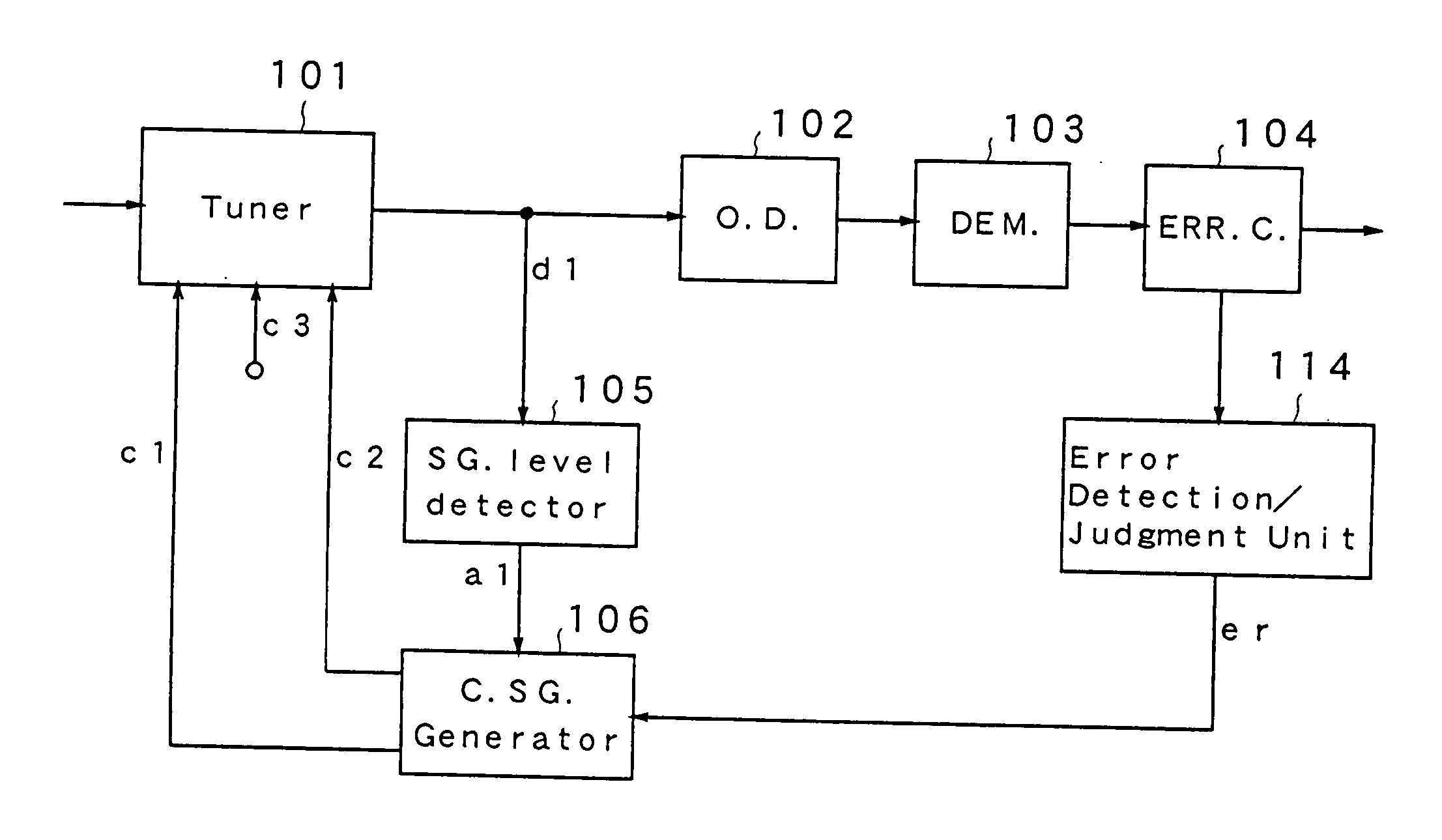
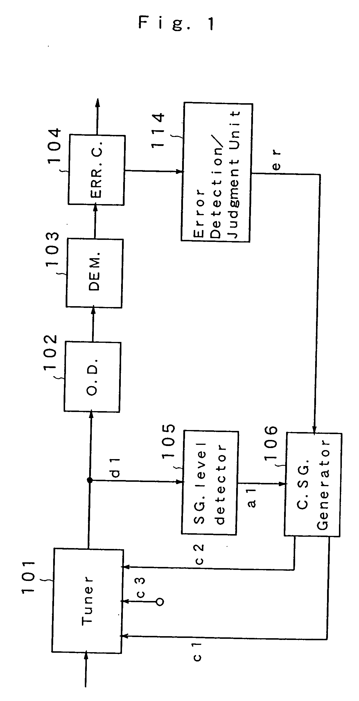
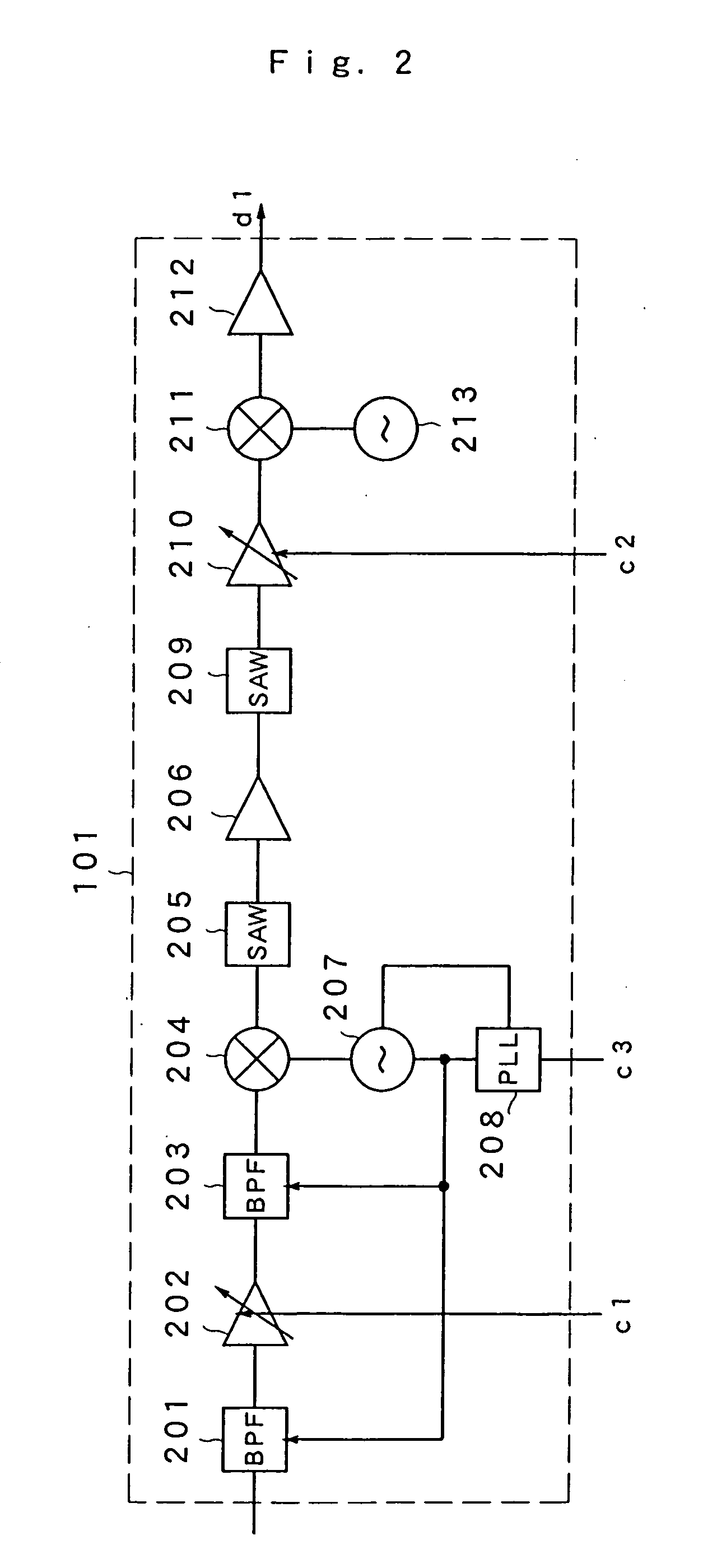
[0057] The digital broadcast receiver shown in FIG. 7 comprises an automatic gain controller 10A, a tuner 101, an orthogonal detector 102, a demodulator 103, and an error corrector 104. The tuner 101 amplifies an input signal to select a RF signal on a desired band and amplifies the RF signal to frequency-converts the RF signal into an IF signal. The orthogonal detector 102 calculates I and Q complex signals from the IF signal of the tuner 101. The demodulator 103 is constituted by an FFT block 103a and an equalizer (EQ) 103b and demodulates a digital signal from the I and Q complex signals of the orthogonal detector 102.

[0058] The automatic gain controller 100A detects a signal level of a reception signal fr...

embodiment 2

[0071] Next, description will be given of a digital broadcast receiver according to Embodiment 2 of the present invention referring to FIG. 10. FIG. 10 is a view illustrating a configuration of the digital broadcast receiver centered around an automatic gain controller according to Embodiment 2.

[0072] The digital broadcast receiver according to Embodiment 2 further comprises, in the digital broadcast receiver shown in FIG. 7, a time axis filter 109 between the orthogonal detector 102 and demodulator 103, and an automatic gain controller 100B, which is different from the automatic gain controller 100A.

[0073] The automatic gain controller 100B includes the signal level detector 105, control signal generator 106, a detection level calculator 110, and a signal level judgment unit 111.

[0074] The time axis filter 109 is constituted by a digital filter. The time axis filter 109, when an output signal of the orthogonal detector 102 is supplied thereto, extracts a signal component on the ...

embodiment 3

[0081] Next, description will be given of a digital broadcast receiver according to Embodiment 3 of the present invention referring to FIG. 12. FIG. 12 is a view illustrating a configuration of the digital broadcast receiver centered around an automatic gain controller according to Embodiment 3.

[0082] The digital broadcast receiver according to the present embodiment comprises a tuner 101C and an automatic gain controller 100C each having a configuration different from those according to Embodiments 1 and 2, in addition to the orthogonal detector 102, demodulator 103, and error corrector 104 in the same manner as in Embodiment 1. The automatic gain controller 100C includes the signal level detector 105 and control signal generator 106. In the present embodiment, the tuner 101C detects the presence of the interference waves in adjacent channels and outputs a adjacent judgment signal h1 to the control signal generator 106 and thereby controls the delay point.

[0083] A delay point con...


PUM


Abstract

A tuner has a dual AGC function, and frequency-converts an input signal into an IF signal. An orthogonal detector calculates a complex signal from the IF signal. A demodulator demodulates a digital signal from the complex signals. An error corrector corrects the error of the digital signal. A signal level detector calculates a level judgment signal from the IF signal. A demodulation level detector detects a signal level of a demodulation signal on a desired band from an output signal of the demodulator. When a demodulation level judgment unit generates a judgment signal representing an influence from interference waves in adjacent channel affecting on a signal on the desired band from the demodulation signal, a control signal generator feeds back a gain control signal to the tuner in accordance with the judgment signal.

Description

TECHNICAL FIELD [0001] The present invention relates to a digital broadcasting receiver centered around an automatic gain controller capable of controlling an influence resulting from adjacent interferences caused by signals in adjacent channel with respect to digital broadcast waves and including a technology for improving a reception characteristic of the digital broadcast waves. BACKGROUND ART [0002] Digitalization of communication technology in recent years has been developed into the field of broadcasting. Digital television digital audio broadcasting services have put into practical use. In Japan, the broadcasting services via broadcast satellites have become available, and various experiments on terrestrial broadcasting toward commercialization have been completed and new broadcasting services have been launched. [0003] Terrestrial digital broadcast waves and analogue broadcast waves will be transmitted simultaneously for some time after the start of its services. In simultan...

Claims


Application Information

Patent Timeline
Patent Type & Authority Applications(United States)
IPC IPC(8): H04N7/173H04N5/50H04N5/08H04N7/16H03G3/30H04N5/44H04N5/52
CPCH03G3/3068H04N5/52H04N5/4401H03G3/3089H04N21/426
Inventor WATANABE, KOUHAYASHI, DAISUKEKATO, HISAYAYAGI, TETSUYA
Owner PANASONIC CORP
Why Eureka
Try Eureka