
Shoulder brace with body to arm attachment straps

a technology of shoulder brace and attachment strap, which is applied in the field of shoulder complex and upper arm injury reduction system, can solve the problems of slow movement of the injured body part, allowing the body part to completely unrestricted free movement, and not being able to stand up to the tremendous physical punishment encountered by the larger athletes of the presen

Active Publication Date: 2006-07-27
SAWA THOMAS M
View PDF19 Cites 20 Cited by
  • Summary
  • Abstract
  • Description
  • Claims
  • Application Information

AI Technical Summary

Benefits of technology

[0007] According to another aspect of the present invention, the torso fitting part includes a shoulder capping region and a control strap which extends from the shoulder capping region to a strap mounting location below the shoulder capping region. Alternatively, the strap can extend from a location below the shoulder capping region to a strap mounting location above the shoulder capping region. The strap is length adjustable to allow tension to be placed on the strap and to produce traction within the system between the shoulder strapping region and the strap mounting location.
[0008] The key to the present invention lies in the use of length adjustable, essentially non-stretch straps, which can be fixedly anchored in position on the system. Through the use of these three features, the straps, while allowing a controlled limited movement of the upper arm wrap part relative to the torso fitting part, are strong enough to control even the biggest and strongest athlete from moving beyond a desired range of motion set by the control straps.

Problems solved by technology

The elasticity of the straps, particularly once the straps are stretched, would slow movement of the injured body part rather than allowing the body part completely unrestricted free motion.
As such, the harness as described in my 1988 patent, although providing extremely beneficial results at the time, is not capable of standing up to the tremendous physical punishment encountered by the larger athletes of the present.

Method used


Image

  • Shoulder brace with body to arm attachment straps
  • Shoulder brace with body to arm attachment straps
  • Shoulder brace with body to arm attachment straps

Examples


Embodiment Construction

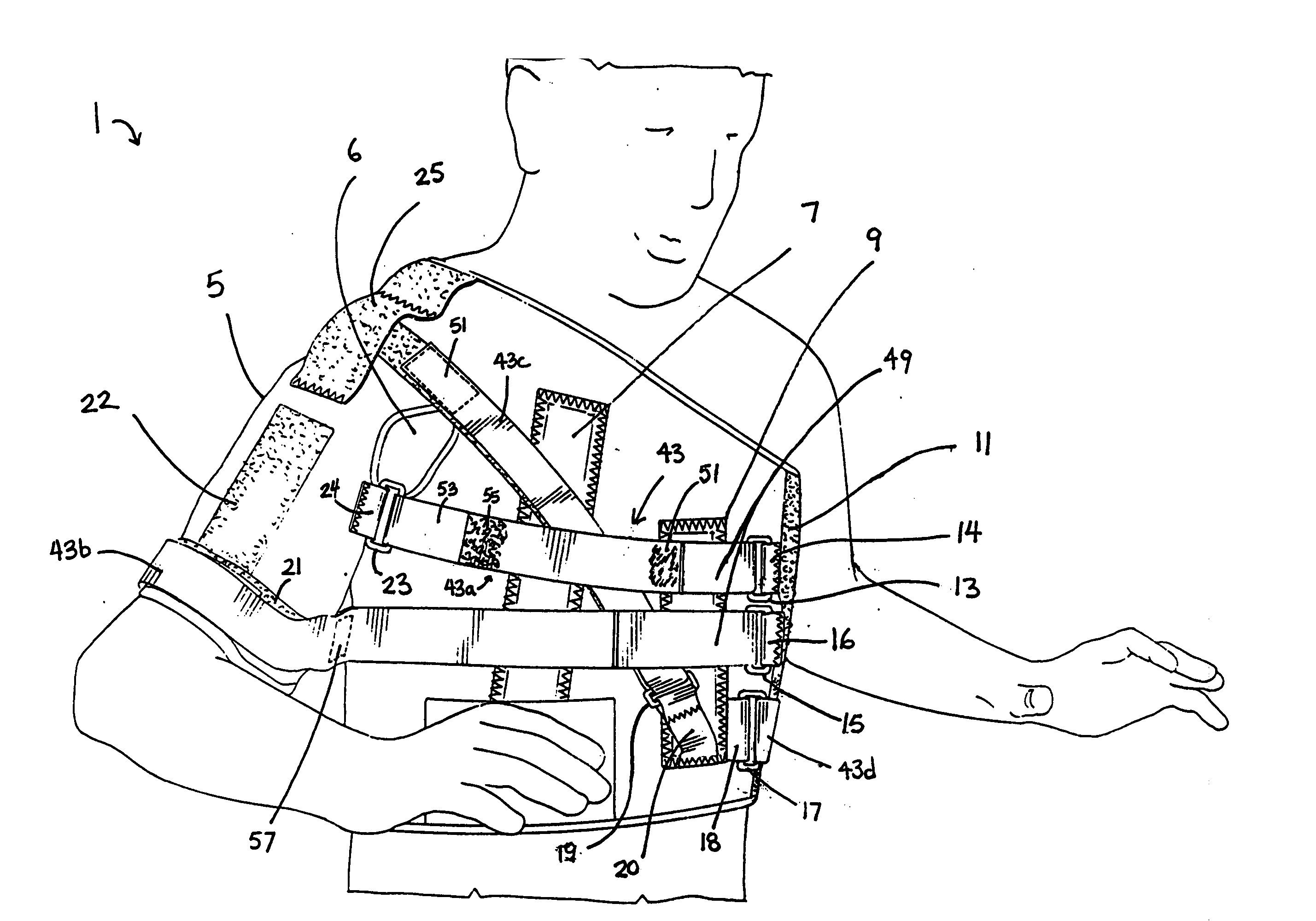
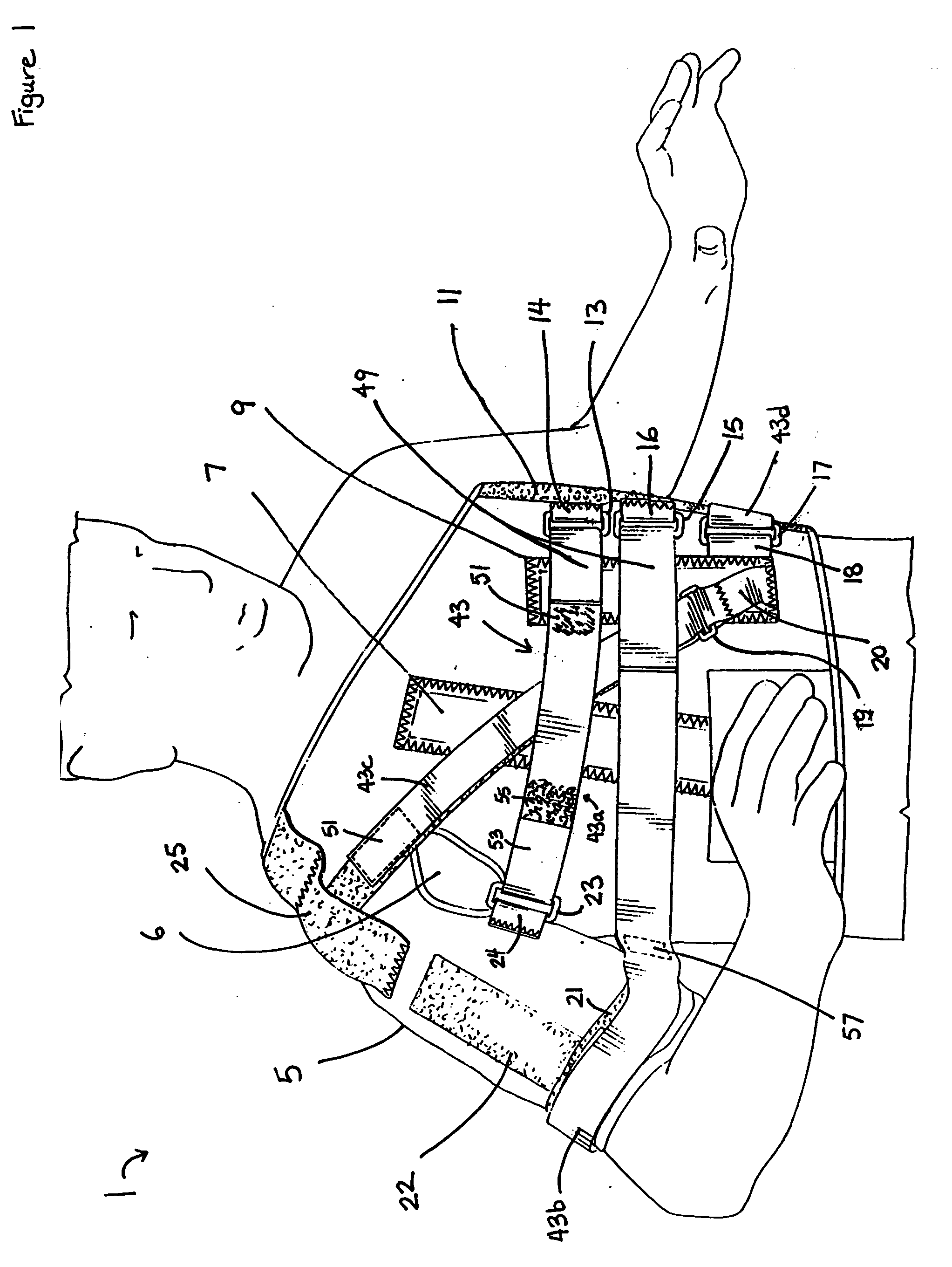
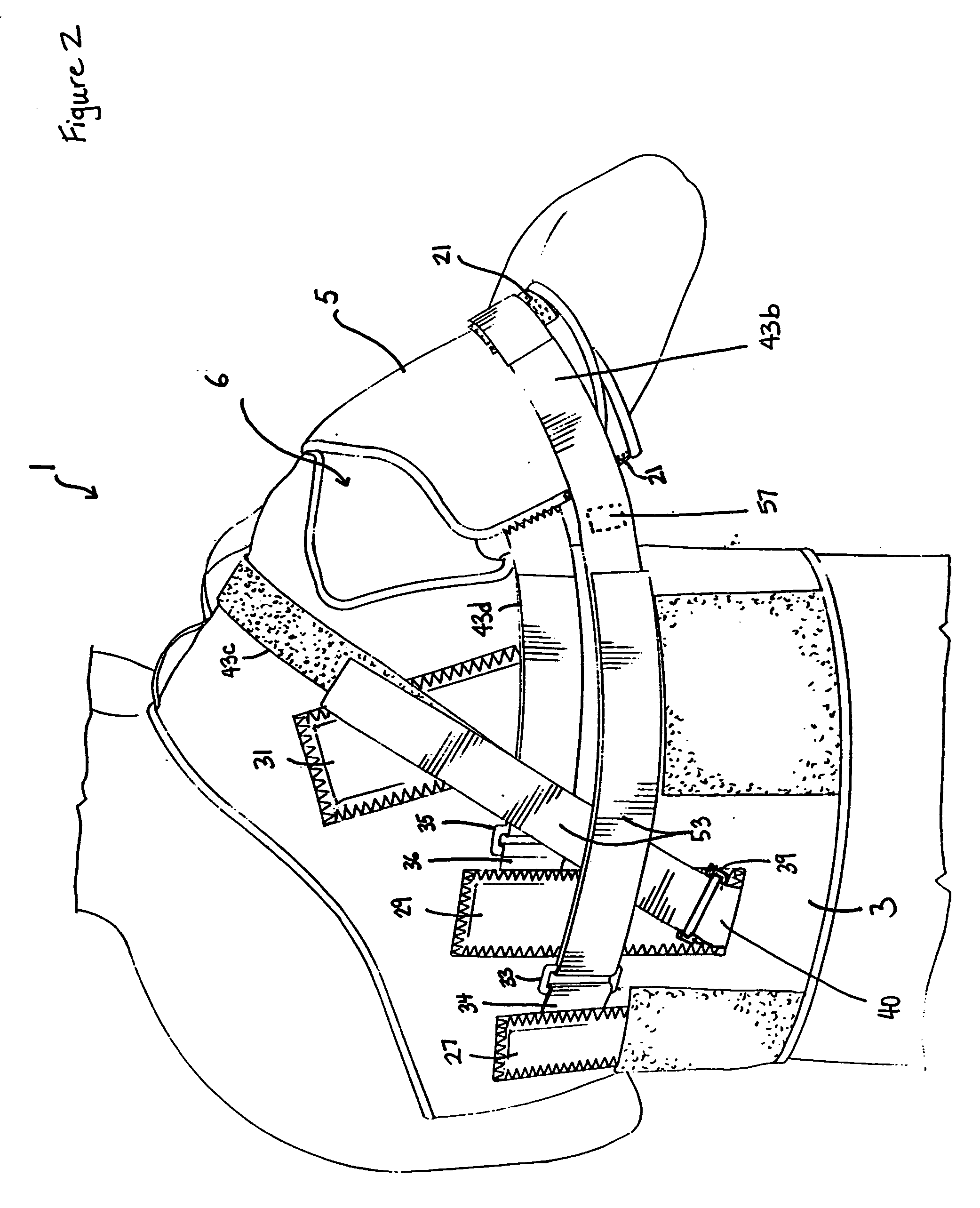
[0024]FIG. 1 shows a shoulder complex and upper arm injury reduction system generally indicated at 1. This system is based on a corset like member comprising a torso fitting part 3 and an upper arm wrap part 5. The torso fitting part 3 and the upper arm wrap part 5, in the embodiment shown in FIG. 1, are part of a one piece corset provided with an underarm cutout 6. This underarm cutout allows movement of the upper arm wrap part 5 relative to the torso fitting part 3 without chaffing in the underarm region.

[0025] Torso fitting part 3 includes a side closure 11 which allows the entire corset to be opened for fitting on to the user including the fitting of the upper arm through part 5. Side closure 11, which is preferably a Velcro™ closure, can then be secured to hold the overall corset tightly wrapped on the body of the user.

[0026] Upper arm wrap part 5 preferably includes a side closure which allows the entire upper arm wrap part to be opened for fitting on to the arm of the user....


PUM


Abstract

A shoulder complex and upper arm injury reduction system having a torso fitting part, an upper arm wrap part, and at least one movement control strap constructed of non-stretchable material. The movement control straps are strategically anchored on the system to control posterior, anterior, and multidirectional movement of the upper arm wrap part relative to the torso fitting part. The straps are length adjustable to control the amount of movement of the upper arm wrap part relative to the torso fitting part, and prevent separation of the upper arm wrap part from the torso fitting part beyond the strap length. The system includes a control strap that extends from the shoulder capping region to a strap mounting location below or above the shoulder capping region. The strap is length adjustable to allow tension to be placed on the strap and to produce traction between the shoulder strapping region and the strap mounting location.

Description

FIELD OF THE INVENTION [0001] The present invention relates to a shoulder complex and upper arm injury reduction system. The system is particularly useful for athletes in contact sports. BACKGROUND OF THE INVENTION [0002] Dating back to 1988, I patented an injury reduction and stabilizing harness as described in my U.S. Pat. No. 4,735,198. According to my earlier patent, I used elastic straps on a torso and upper arm fitting harness to control the amount of movement of the upper arm relative to the torso of the user. The straps, according to my earlier patent, attached at their opposite ends by Velcro™ to different part of the harness. [0003] My earlier patented harness allowed athletes or even people under general rehabilitation continued controlled use of an injured shoulder or upper arm. The elasticity of the straps, particularly once the straps are stretched, would slow movement of the injured body part rather than allowing the body part completely unrestricted free motion. [000...

Claims


Application Information

Patent Timeline
Patent Type & Authority Applications(United States)
IPC IPC(8): A61F5/00A61F13/00A61F13/06
CPCA61F5/34A61F5/3746
Inventor SAWA, THOMAS M.
Owner SAWA THOMAS M
Learn More