Automatic chute opening system for strapping machine

Inactive Publication Date: 2007-09-04
ILLINOIS TOOL WORKS INC
View PDF2 Cites 26 Cited by
  • Summary
  • Abstract
  • Description
  • Claims
  • Application Information

AI Technical Summary

Benefits of technology

[0016]The benefits and advantages of the present invention will become more readily apparent to those of ordinary

Problems solved by technology

In the event a strap error occurs, the faulted strap is ejected from the strapping machine by the feed system.
One drawback to this arrangement is that a “lighter” work surface is more likely to pivot slightly open which in

Method used


Image

  • Automatic chute opening system for strapping machine
  • Automatic chute opening system for strapping machine
  • Automatic chute opening system for strapping machine

Examples


Embodiment Construction

[0022]While the present invention is susceptible of embodiment in various forms, there is shown in the figures and will hereinafter be described a presently preferred embodiment with the understanding that the present disclosure is to be considered an exemplification of the invention and is not intended to limit the invention to the specific embodiment illustrated.

[0023]It should be further understood that the title of this section of the specification, namely, “Detailed Description Of The Invention”, relates to a requirement of the United States Patent Office, and does not imply, nor should be inferred to limit the subject matter disclosed herein.

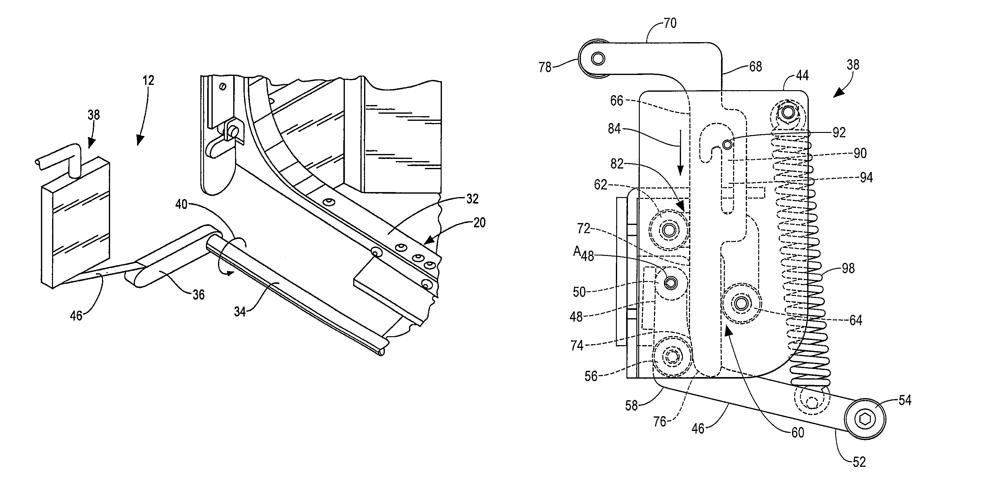
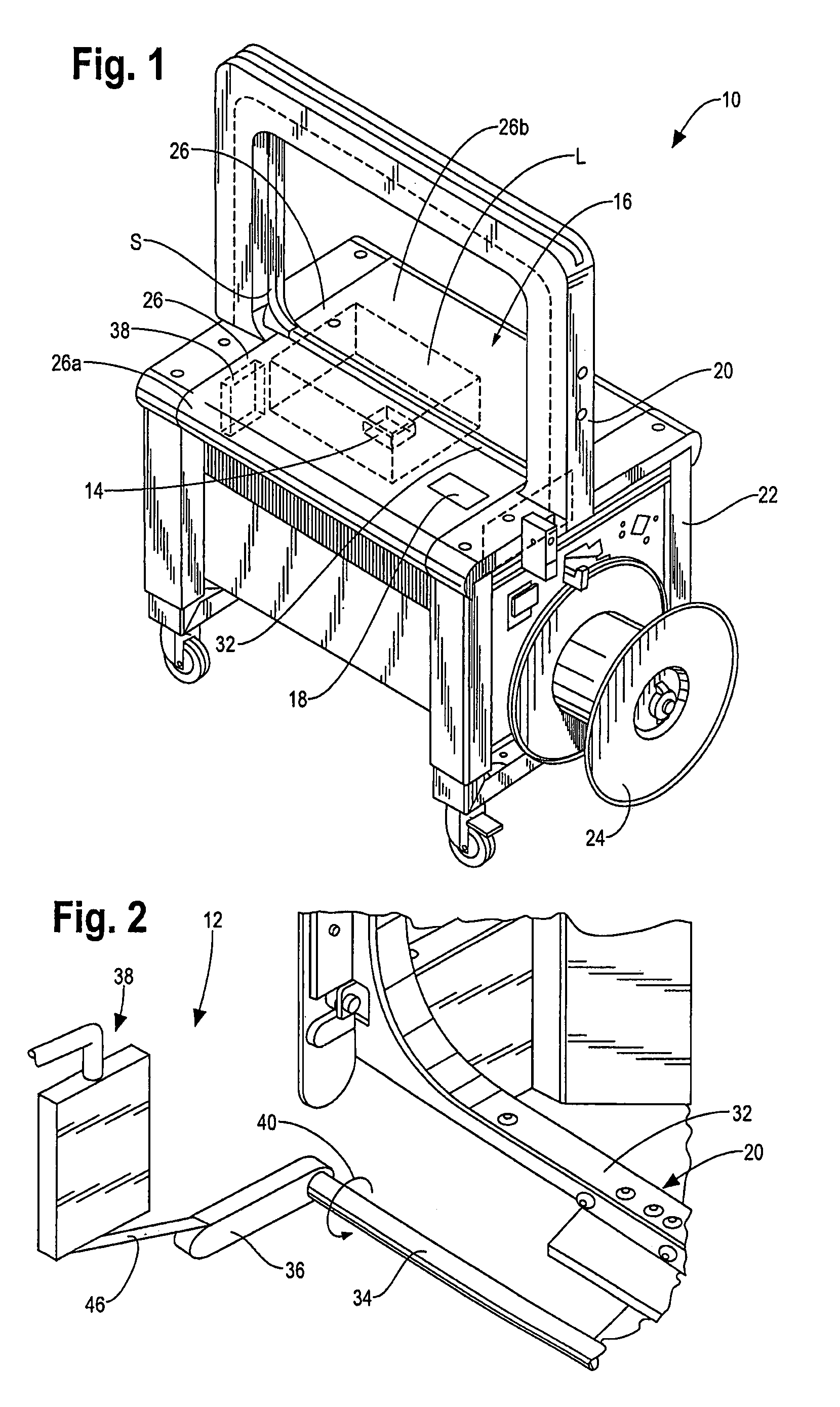
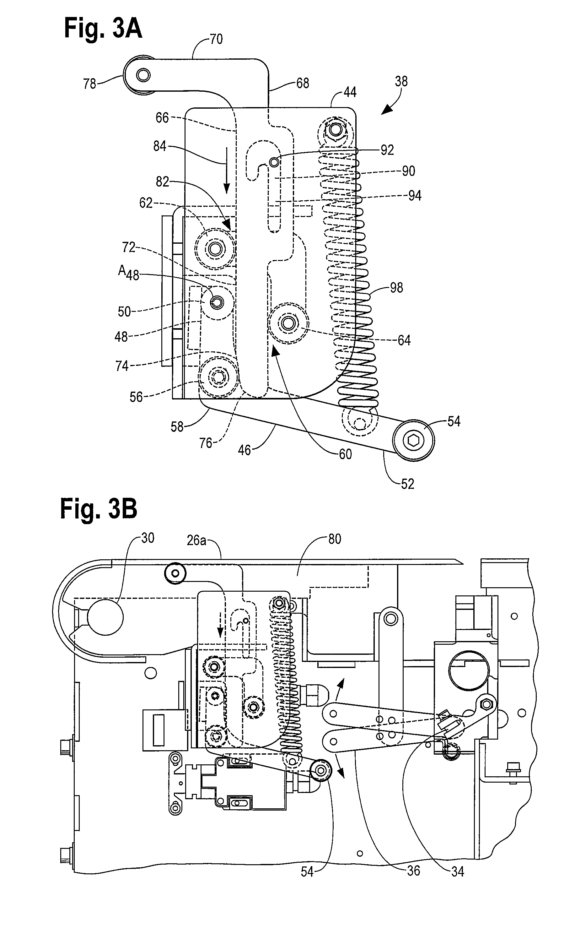
[0024]Referring to the figures and in particular to FIG. 1 there is shown a strapping machine 10 having an automatic chute opening system 12 in accordance with the principles of the present invention. The illustrated machine 10 is a bottom-seal strapper, meaning that the strapping head 14 (or sealing head), which forms the seal of the stra...


PUM


Abstract

An automatic strap chute opening system for use in a strapping machine of the type having an openable, pivotable work surface for supporting a load to be strapped, and a strap chute defining a strap path through which the strapping material is passed. The chute is disposed in part below the surface and is openable to release the strapping material from the chute during the strapping operation. The chute opening system includes a torsional element operably connected to the strap chute for opening and closing the chute and an actuator operably connected to the torsional element. The coordinated movement of the actuator and torsional element corresponds with the opening or closing of the work surface.

Description

BACKGROUND OF THE INVENTION[0001]The present invention is directed to a strapping machine chute opening system. More particularly, the present invention is directed to a strapping machine having a chute opening system that automatically opens the strap chute upon opening the work surface or table top of the machine.[0002]Strapping machines are well known in the art for securing straps around loads. One type of known strapper is a stationary unit that includes a strapping head or weld head and drive mechanism mounted within a frame. A chute is mounted to the frame, through which the strapping material is fed. In a typical arrangement, a table-top or work surface is likewise mounted to the frame.[0003]In a typical stationary strapper, the chute is mounted from about the work surface, and the strapping head is mounted below the work surface. Strap is fed (by a feed system) from a source or dispenser through the strapping head and chute and back to the strapping head, to pull the strap ...

Claims


Application Information

Patent Timeline
IPC IPC(8): B65B13/04B65B13/18
CPCB65B13/06
Inventor HOLDEN, DAVID W.BOBREN, ALLAN J.
Owner ILLINOIS TOOL WORKS INC
Why Eureka
Try Eureka