Acoustic liner with a nonuniform depth backwall

a backwall and acoustic liner technology, applied in the field of noise attenuating liners, can solve the problems of engine noise, objectionable noise, and ineffectiveness of acoustic liner, and achieve the effect of reducing noise in the duct without introducing undue weight, cost or complexity, and without jeopardizing the aerodynamic performance of the du

Inactive Publication Date: 2006-08-03
UNITED TECH CORP
View PDF10 Cites 36 Cited by
  • Summary
  • Abstract
  • Description
  • Claims
  • Application Information

AI Technical Summary

Benefits of technology

[0010] It is, therefore, an object of the invention to redirect reflected noise in a duct without introducing undue weight, cost or complexity and without jeopardizing the aerodynamic performance of the duct.

Problems solved by technology

During operation, the engine generates noise that propagates to the environment through the open ends of the ducts.
Because the noise is objectionable, engine manufacturers install acoustic liners on portions of the interior walls of the ducts.
Acoustic liners are not completely effective.
Some of the noise decays too rapidly with distance to propagate outside the ducts.
Moreover, the reflected signal decays exponentially with distance due to the inability of sound at that frequency to propagate in the duct at that angle.
For example if a noise signal strikes the liner close to the open end of the duct (i.e. near the intake plane of an inlet duct or near the exhaust plane of an exhaust duct) the axial distance between the point of incidence and the open end of the duct may be too small to intercept a reflected signal, even one reflected at a steep angle.
However such liners are not completely satisfactory because their capability is limited by the power available to drive the actuators.
Moreover, the active backwall introduces unwelcome weight, cost and complexity.
However doing so is almost always impractical because the interior shape of the duct is governed by aerodynamic considerations.
Because the liner face sheet defines at least part of the contour of the duct interior wall, orienting the entire liner to regulate the direction of reflected noise will almost always compromise the aerodynamic performance of the duct.

Method used


Image

  • Acoustic liner with a nonuniform depth backwall
  • Acoustic liner with a nonuniform depth backwall
  • Acoustic liner with a nonuniform depth backwall

Examples


Embodiment Construction

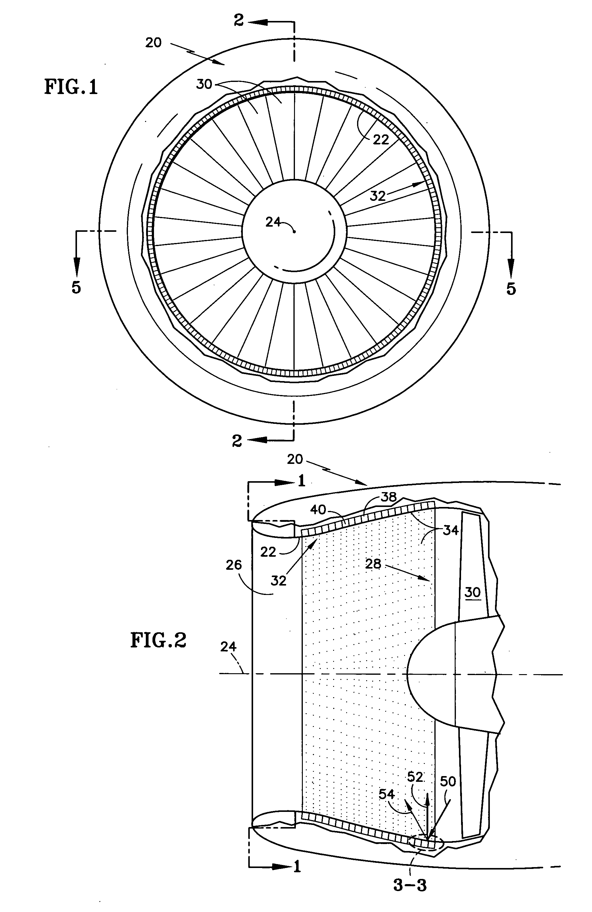
[0028]FIGS. 1, 2 and 5 illustrate a turbine engine inlet duct 20 defined by duct interior wall 22, which circumscribes a duct axis 24. The illustrated inlet duct is substantially circular in cross section when viewed parallel to the engine axis, although some inlet ducts have a noticeably less circular shape. One end 26 of the duct is open to the atmosphere. The other end of the duct, which is axially offset from the open end, is immediately forward of a compressor represented by a rotatable fan 28 having an array of blades 30. During engine operation the fan is a source of noise.

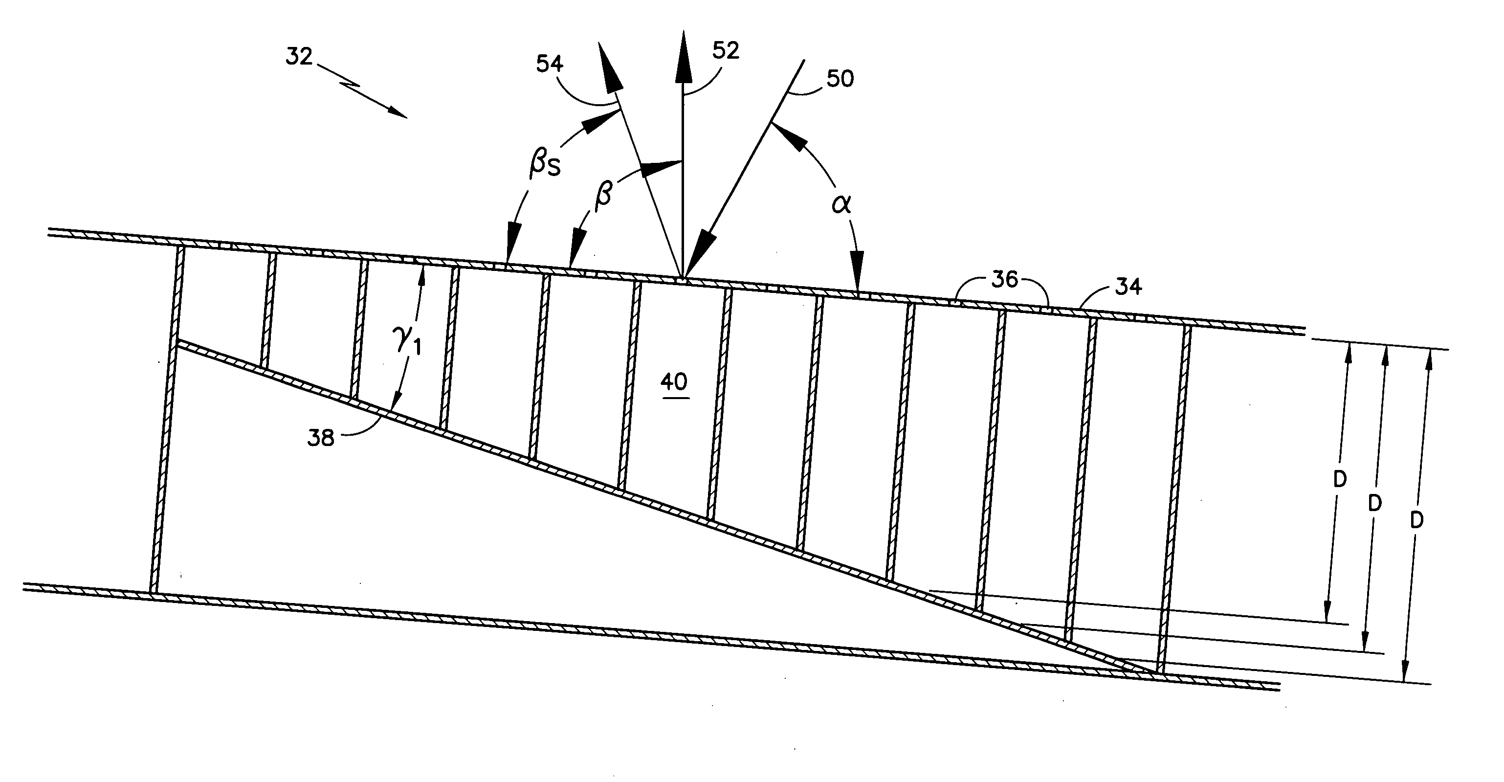
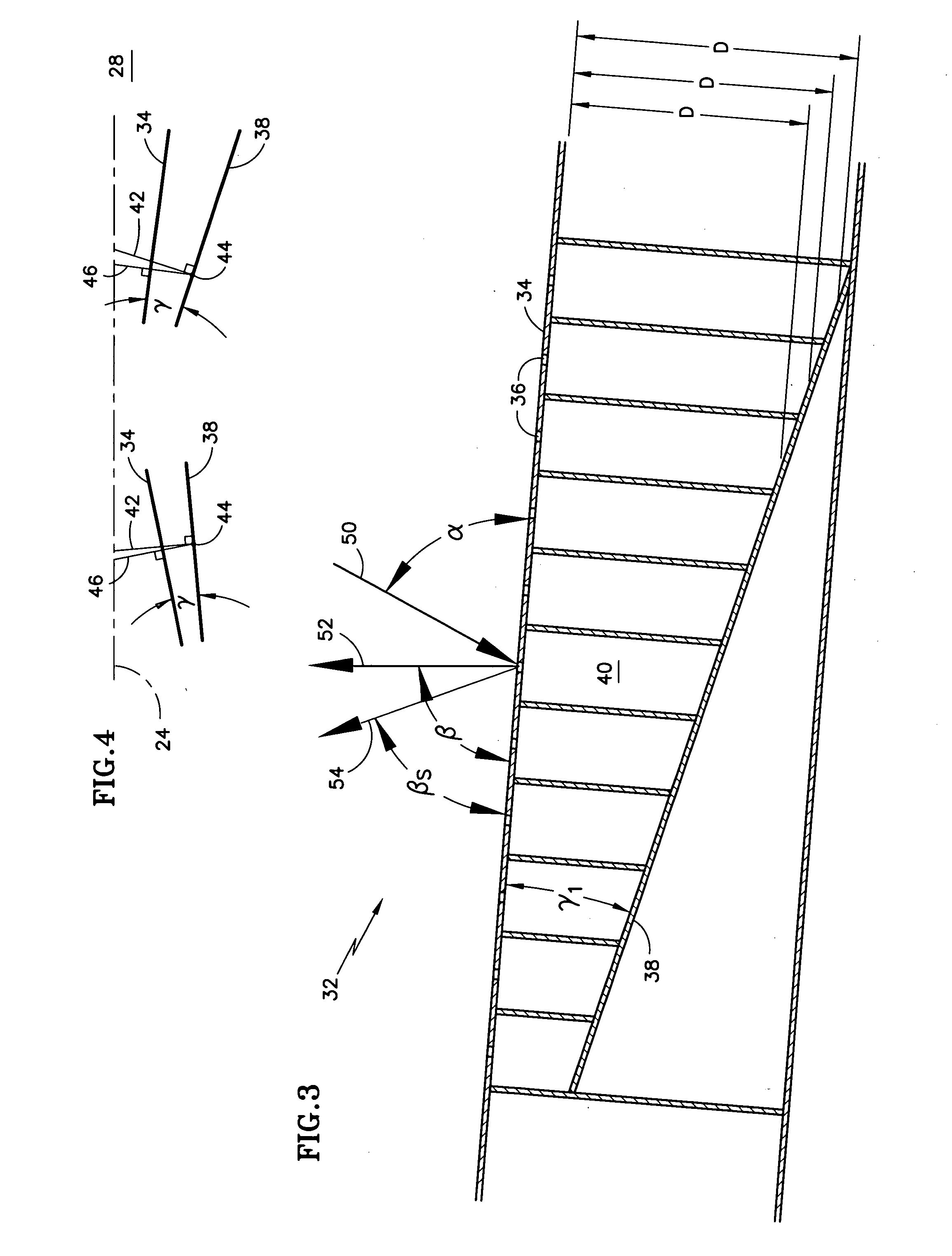
[0029] Portions of the duct interior wall 22 are lined with an acoustic liner 32. A typical acoustic liner comprises a face sheet 34 perforated by numerous small holes 36 (visible in FIGS. 3 and 6) and an imperforate back sheet or backwall 38 spaced from the face sheet. The face sheet defines the interior contour of the duct wall as seen best in FIGS. 2 and 5. An array of resonator chambers 40 or other sou...


PUM


Abstract

A fluid handling duct such as a turbine engine inlet duct 20 includes an acoustic liner 32 comprising a face sheet 34 and a backwall 38 laterally spaced from the face sheet. The backwall is offset from the face sheet by a nonuniform depth D to direct sound waves incident on the backwall in a prescribed direction relative to the face sheet. In one embodiment of the invention, the backwall comprises a ramp. In another embodiment, the backwall comprises a series of steps offset from the face sheet by different depths. The nonuniform depth of the backwall may be tailored to regulate the direction in which noise signals reflect from the backwall, thereby reducing noise propagation from the duct to the surrounding environment.

Description

CROSS REFERENCE TO RELATED APPLICATIONS [0001] This application includes subject matter in common with commonly owned, co-pending application entitled “Acoustic Liner with Nonuniform Impedance” (Assignee's docket number EH-11451) filed concurrently herewith.TECHNICAL FIELD [0002] This invention relates to noise attenuating liners for fluid handling ducts such as the inlet and exhaust ducts of turbine engines. BACKGROUND OF THE INVENTION [0003] Turbine engines, such as those used for aircraft propulsion, include an inlet duct for delivering air to the engine and an exhaust duct for discharging combustion products to the atmosphere. During operation, the engine generates noise that propagates to the environment through the open ends of the ducts. Because the noise is objectionable, engine manufacturers install acoustic liners on portions of the interior walls of the ducts. A commonly used type of acoustic liner features an array of resonator chambers sandwiched between a perforated fa...

Claims


Application Information

Patent Timeline
Patent Type & Authority Applications(United States)
IPC IPC(8): G10K11/00B64F1/26E04F17/04B64D33/02E04H17/00F02K11/00F02K99/00
CPCB64D33/02B64D2033/0206B64D2033/0286F02C7/045F02K1/44F02K1/827F16L55/02727F16L55/033G10K11/172F05D2260/96F05D2250/283
Inventor PATRICK, WILLIAM P.
Owner UNITED TECH CORP
Why Eureka
Try Eureka