Clip device for securing a diaphragm hunting call and the like

Inactive Publication Date: 2006-08-10
HERMAN JOHN C
6 Cites 4 Cited by

AI-Extracted Technical Summary

Problems solved by technology

If a hunter has to search and find the essential gear, valuable time is wasted and the opportunity for bagging the desi...

Method used

[0021] As illustrated in FIGS. 1 and 5, the clip device 10 of the present invention additionally includes a first clip arm 24 and a second clip arm 26 extending from the supporting wall 20 in a cantilever manner over the top surface 12 of the clip device 10. The first clip arm 24 is preferably spaced from the second clip arm 26 with each clip arm 24, 26 having a protruding portion 28 for maintaining the position of the clip device 10 relative to the mounting location, such as a brim (not shown) of a hat (not shown) or other garm...

Abstract

A clip device for securing an item is provided. The clip device is securable to an object. The clip device comprises a main body having a top surface, a bottom surface, a front edge, and a back edge. A supporting wall extends from the front edge in general direction away from the top surface. A clip mechanism extends from the supporting wall over the top surface for securing the clip device to an object. An item retaining mechanism extends substantially along the back edge for releasably securing the item within the lip portion adjacent and against the bottom surface of the main body.

Application Domain

Travelling carriersAnimal hunting +2

Technology Topic

Clip deviceTrailing edge +3

Image

  • Clip device for securing a diaphragm hunting call and the like
  • Clip device for securing a diaphragm hunting call and the like
  • Clip device for securing a diaphragm hunting call and the like

Examples

  • Experimental program(1)

Example

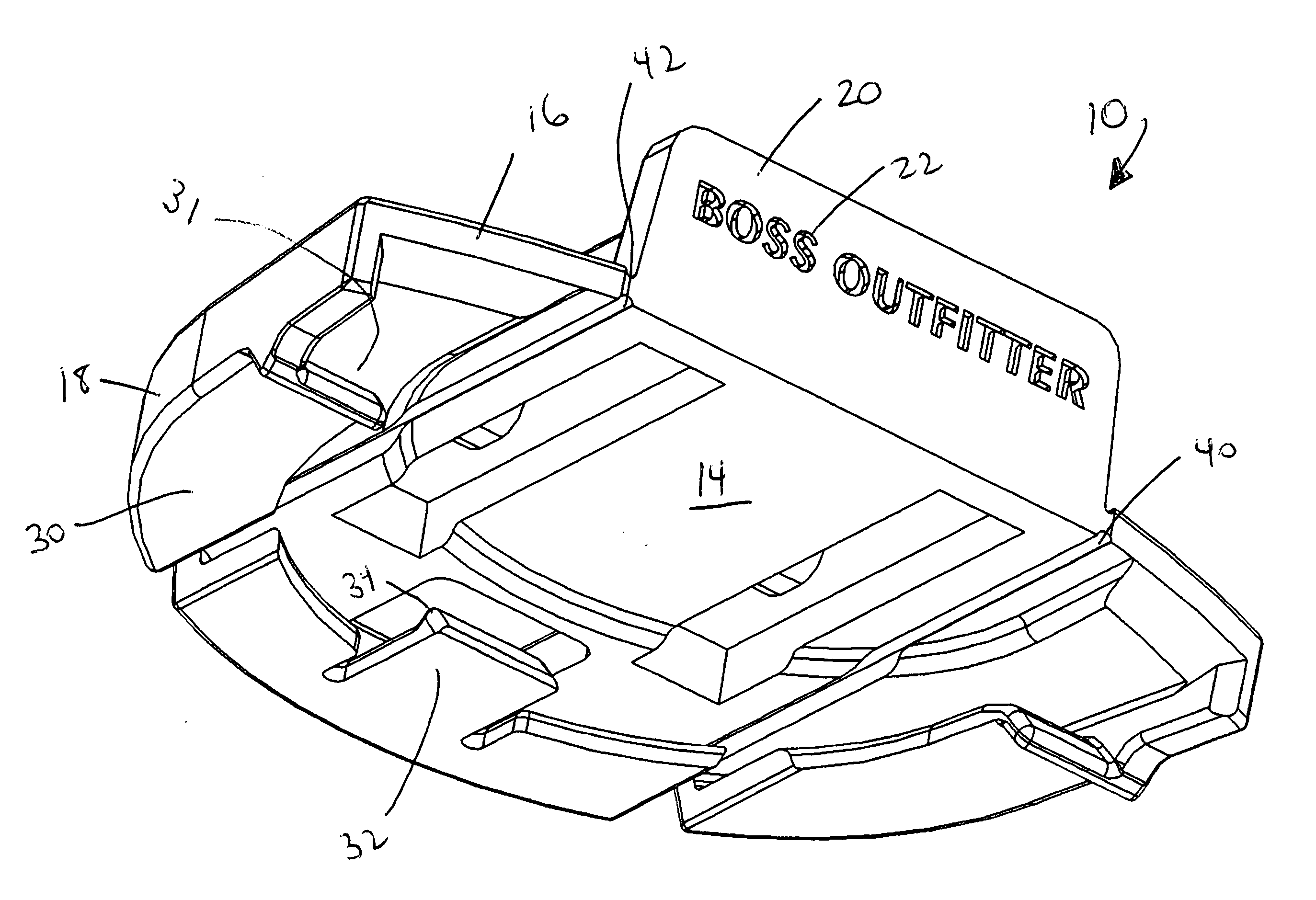
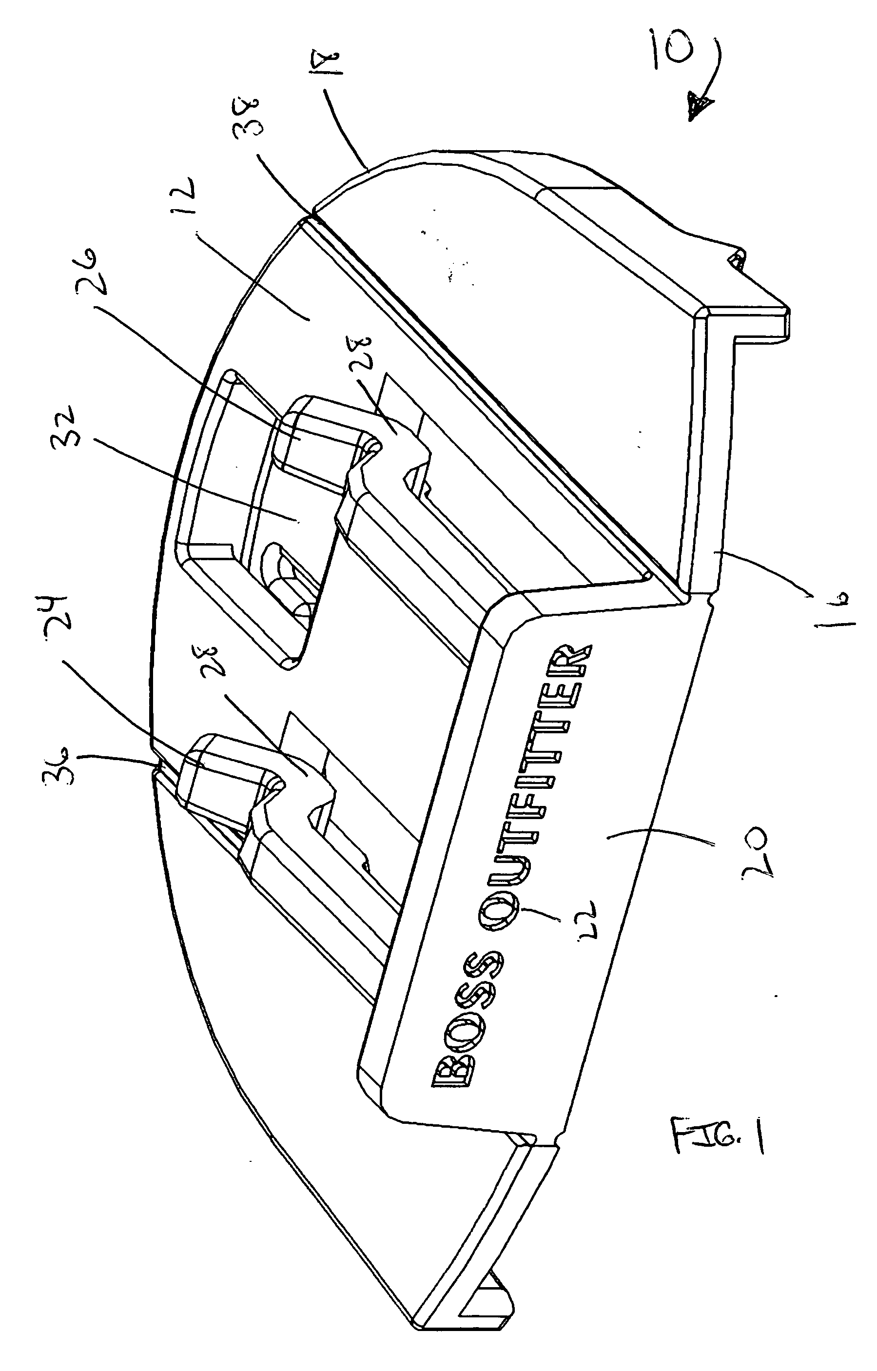
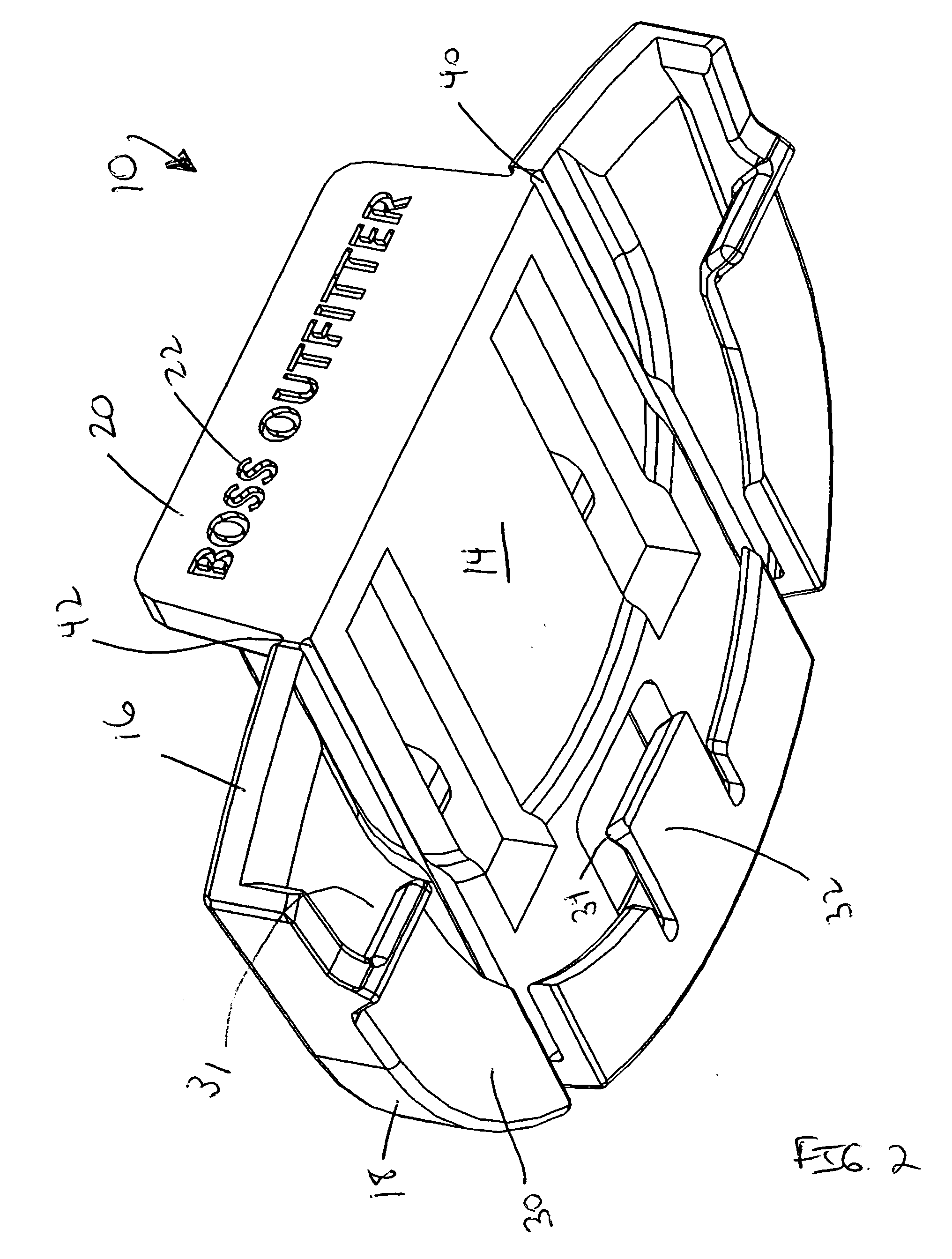
[0018] As illustrated in FIGS. 1 and 2, the present invention is a clip device, indicated generally at 10, for securing a diaphragm hunting call (not shown) or the like. Preferably, the clip device 10 of the present invention is molded from a durable plastic material having sufficient strength and flexibility for mounting to a garment (not shown). However, it is within the scope of the present invention to construct the clip device 10 from other materials including, but not limited to, metal, fiberglass, ceramics, resin, wood, etc.
[0019] It should be noted that while the clip device 10 of the present invention has been described hereto and will be described hereafter as securing a diaphragm hunting call, a person skilled in the art will understand that the clip device 10 of the present invention can be used to secure other objects. In fact, the clip device 10 of the present invention is suitable for securing a wide variety of essentials such fishing lures, i.e., flies, fishing line, and the like, flashlights, emergency medical supplies, etc.
[0020] As illustrated in FIGS. 1, 2, 3, and 4, the clip device 10 of the present invention has a top surface 12, a bottom surface 14, a front edge 16, and a curved back edge 18. A supporting wall 20 extends from the front edge 16 of the top surface 12 in general direction away from the top surface 12. The supporting wall 20 can carry advertisements or endorsements 22 thereon, if so desired.
[0021] As illustrated in FIGS. 1 and 5, the clip device 10 of the present invention additionally includes a first clip arm 24 and a second clip arm 26 extending from the supporting wall 20 in a cantilever manner over the top surface 12 of the clip device 10. The first clip arm 24 is preferably spaced from the second clip arm 26 with each clip arm 24, 26 having a protruding portion 28 for maintaining the position of the clip device 10 relative to the mounting location, such as a brim (not shown) of a hat (not shown) or other garment. The first clip arm 24 and the second clip arm 26 are free from contact with the top surface 12 of the clip device 10 which allows the clip device 10 to be easily releasably secured to the hat without requiring the user to manipulate or otherwise open the clips. Furthermore, having two clip arms 24, 26 provide more secure mounting of the clip device 10 to the hat in case the clip device 10 as compared to only one clip arm. Actual mounting of the clip device 10 to the brim of the hat will be described in further detail below.
[0022] As illustrated in FIGS. 2 and 4, the clip device 10 of the present invention includes lip portion 30 extending substantially along the curved back edge 18 of the clip device 10 and defining a receiving slot 31. The receiving slot 31 is preferably tapered to frictionally hold the diaphragm hunting call therein. The lip portion 30 and the receiving slot 31 allows a diaphragm hunting call to be releasably secured within the lip portion 30 to the clip device 10 adjacent and against the bottom surface 14 of the clip device 10, as will be described in further detail below. A retaining tab 32 having a retaining protrusion 34 extends from the lip portion 30. The retaining tab 32 and the retaining protrusion 34 further secures the diaphragm hunting call within the clip device, as will be described in further detail below.
[0023] As illustrated in FIGS. 6 and 7, the top surface 12 of the clip device 10 includes a first slot 36 and a second slot 38 along the length of the top surface 12 on each side of the supporting wall 20. Furthermore, the bottom surface 14 of the clip device 10 includes a first slot 40 and a second slot 42 opposite the first slot 36 and the second slot 38 of the top surface 12 along the length of the bottom surface 14. It should be noted, as illustrated in FIG. 2, that the first slot 40 and the second slot 42 of the bottom surface 14 extend through the lip portion 30 around the curved back edge 18 of the clip device 10. The slots 36, 38, 40, 42 of the top surface 12 and the bottom surface 14 allow the clip device 10 to bend and flex to accommodate a variety of brim sizes and curvature when mounting to the brim of the hat. The hunting call is not received within the slots.
[0024] Securing the clip device 10 of the present invention to the brim or a hat or the like will now be discussed. As will be understood by a person skilled in the art, the description below is only one manner of securement of the clip device 10 to the brim of the hat and other manners of securement of the clip device 10 are within the scope of the present invention.
[0025] First, the clip device 10 of the present invention is positioned adjacent the brim of the hat with the curved back edge 18 adjacent the brim. The clip device 10 is then manipulated such that the brim is releasably received between first clip arm 24 and the second clip arm 26 and the top surface 12 of the clip device 10. The clip device 10 is further moved onto the brim until the brim contacts the supporting wall 20. The protruding portions 28 of the first clip arm 24 and the second clip arm 26 contacts the brim thereby releasably securing the clip device 10 to the brim.
[0026] Next, the diaphragm hunting call is slid along the bottom surface 14 of the clip device 10 within the lip portion 30 and under the retaining tab 32. The snug fit between the diaphragm hunting call and the lip portion 30 and the retaining protrusion 34 of the retaining tab 32 releasably maintain the diaphragm hunting call within the clip device 10.
[0027] With the clip device 10 of the present invention, the diaphragm hunting call is readily available for use by the hunter. The hunter maintains easy access to the diaphragm hunting call without having to search and retrieve the diaphragm hunting call from an inconvenient location. Furthermore, with the clip device 10 of the present invention, the hunter can retrieve the hunting call without having to place the hunting gun or rifle in an inconvenient or dangerous position.
[0028] The foregoing exemplary descriptions and the illustrative preferred embodiments of the present invention have been explained in the drawings and described in detail, with varying modifications and alternative embodiments being taught. While the invention has been so shown, described and illustrated, it should be understood by those skilled in the art that equivalent changes in form and detail may be made therein without departing from the true spirit and scope of the invention, and that the scope of the present invention is to be limited only to the claims except as precluded by the prior art. Moreover, the invention as disclosed herein, may be suitably practiced in the absence of the specific elements which are disclosed herein.

PUM

no PUM

Description & Claims & Application Information

We can also present the details of the Description, Claims and Application information to help users get a comprehensive understanding of the technical details of the patent, such as background art, summary of invention, brief description of drawings, description of embodiments, and other original content. On the other hand, users can also determine the specific scope of protection of the technology through the list of claims; as well as understand the changes in the life cycle of the technology with the presentation of the patent timeline. Login to view more.
Why Eureka
Try Eureka