
Fan monitoring for failure prediction

a technology for failure prediction and fan monitoring, which is applied in the direction of automatic disconnection emergency protection arrangements, dynamo-electric motor/converter starters, etc., can solve the problems of increasing maintenance costs, affecting the reliability of the entire power supply system, and relatively low reliability of the fan

Active Publication Date: 2006-08-10
HEWLETT-PACKARD ENTERPRISE DEV LP
View PDF8 Cites 55 Cited by
  • Summary
  • Abstract
  • Description
  • Claims
  • Application Information

AI Technical Summary

Problems solved by technology

Fans are a relatively low reliability component in a power supply system.
Failure of one or more fans in a fan array may cause an entire power supply system to fail due to overheating.
Conventionally, fans are often replaced at regular maintenance intervals to avoid fan failure, sometimes replacing good fans and increasing maintenance costs while failing to replace fans that fail at a rate higher than expected.
However, a maintenance schedule that depends on waiting until a FRU fails subjects a user to down-time and possible damage upon occurrence of a random failure event.
However, many or most fan failures occur due to wearing or aging and, although a first failing fan may be replaced, other redundant fans are also likely to be near end-of-life.

Method used


Image

  • Fan monitoring for failure prediction
  • Fan monitoring for failure prediction
  • Fan monitoring for failure prediction

Examples


Embodiment Construction

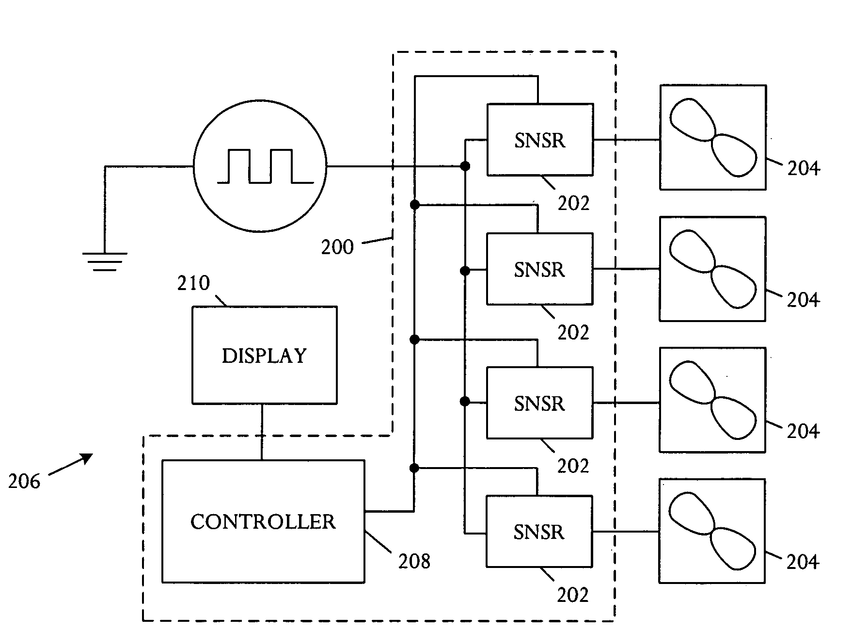
[0012] A fan monitoring device and operating method predict an impending fan failure and enable a customer or user to schedule repair events at a convenient time and setting. In some embodiments, a response to detected impending failure may be automatic, without user action. The fan monitoring device includes a circuit adapted to measure power or current usage of a fan and a control element adapted to perform a failure prediction method or technique.

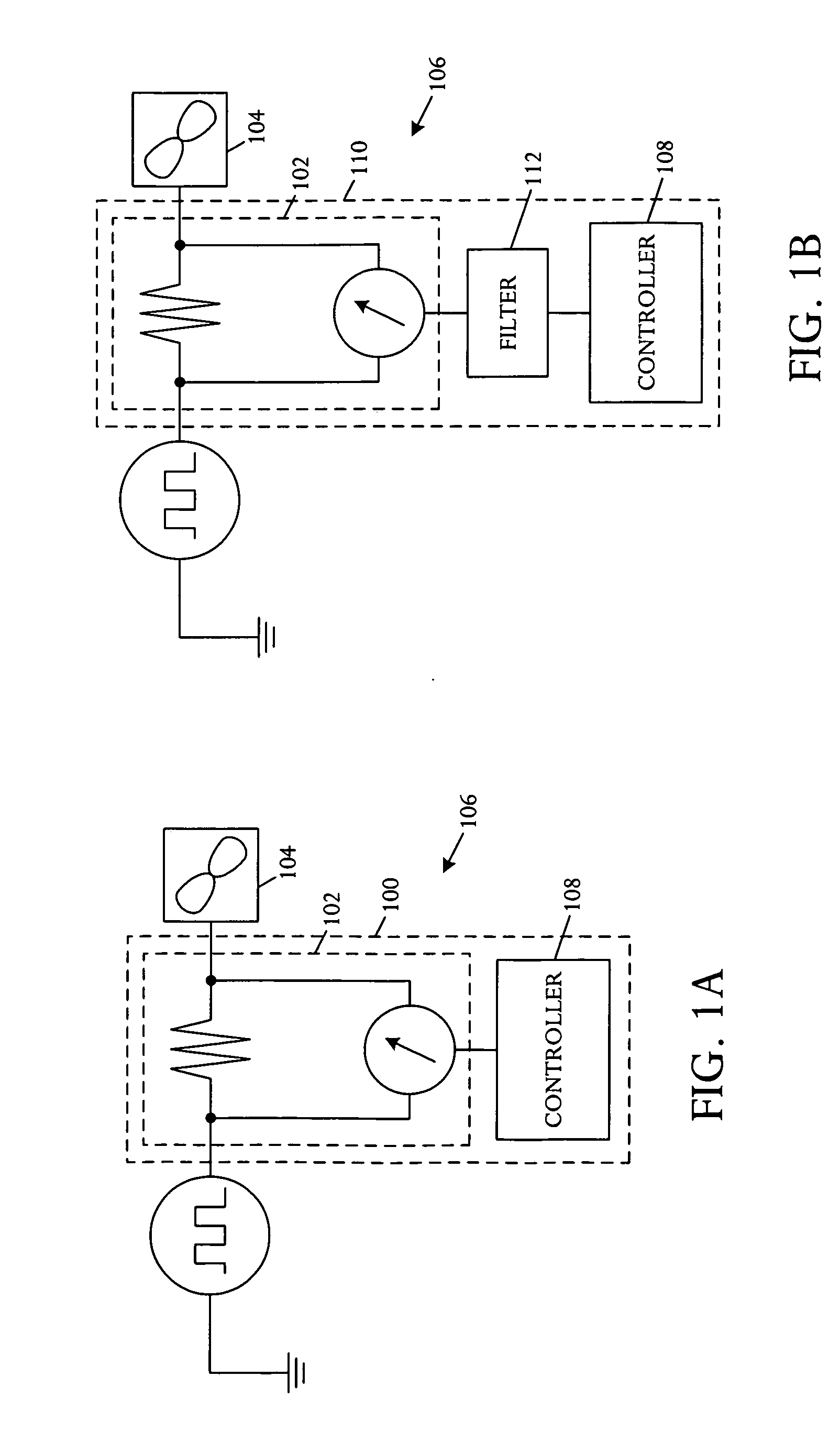
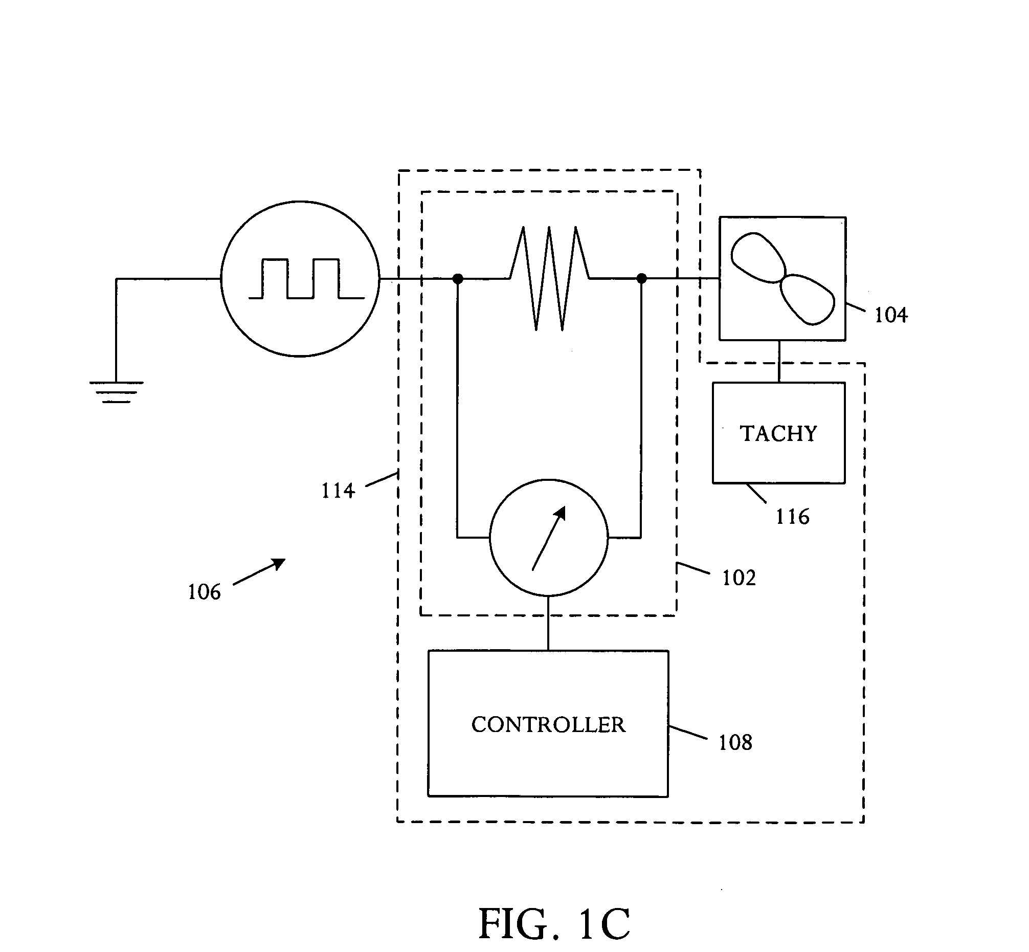
[0013] Referring to FIG. 1A, a schematic block diagram illustrates an embodiment of a fan condition monitoring apparatus 100. A power sensor 102 is adapted for coupling to at least one fan 104 in an electronic system 106 and measures fan power usage. The monitoring apparatus 100 further includes a controller 108 coupled to the power sensor 102 and adapted to determine a derivative of the measured fan power usage, track the derivative over time, and predict impending fan failure based on the tracked fan power usage derivative.

[0014] In ...


PUM


Abstract

A method for monitoring a fan comprises measuring power usage of the fan, determining a derivative of the measured fan power usage, tracking the derivative over time, and predicting impending fan failure based on the tracked fan power usage derivative.

Description

BACKGROUND OF THE INVENTION [0001] Fans are a relatively low reliability component in a power supply system. Failure of one or more fans in a fan array may cause an entire power supply system to fail due to overheating. Conventionally, fans are often replaced at regular maintenance intervals to avoid fan failure, sometimes replacing good fans and increasing maintenance costs while failing to replace fans that fail at a rate higher than expected. [0002] In highly available system, an ability to hot-swap and cold-swap failed field replaceable units (FRUs) is common and useful. However, a maintenance schedule that depends on waiting until a FRU fails subjects a user to down-time and possible damage upon occurrence of a random failure event. Accordingly, many systems use hot-swap FRUs, enabling the system to continue to run during failure and repair. However, many or most fan failures occur due to wearing or aging and, although a first failing fan may be replaced, other redundant fans a...

Claims


Application Information

Patent Timeline
Patent Type & Authority Applications(United States)
IPC IPC(8): G08B21/00G01P3/46G01R31/14
CPCF04D27/004H02H1/0053H02H3/44H02H7/08H05K7/20209H05K7/20836F05D2270/335Y02B30/70
Inventor LARSON, THANE M.MALONE, CHRISTOPHER G.
Owner HEWLETT-PACKARD ENTERPRISE DEV LP
Learn More