Combination light fixture and motion sensor apparatus

a motion sensor and light fixture technology, applied in the field of light fixtures and lighting controls, can solve the problems of reducing the reliability of the system, affecting the ability of people to enter the closet to find what they are looking, so as to save energy

Inactive Publication Date: 2006-08-10
ARRUDA STEVEN S
View PDF3 Cites 49 Cited by
  • Summary
  • Abstract
  • Description
  • Claims
  • Application Information

AI Technical Summary

Benefits of technology

[0007] Accordingly, a preferred embodiment of the present invention provides a combination light fixture and motion sensor apparatus contained in a single enclosure, which turns on automatically when approached, for convenience, and which turns off automatically when the area is vacated, for energy-saving purposes. In particular, this apparatus is one that can be mounted in a bathroom closet, closet, pantry, cabinet, under a cabinet, or an area where wiring a separate light and switch is not feasible or practicable. The combination light fixture and motion sensor apparatus is contained within a single enclosure, and the apparatus may be mounted inside a closet and above the closet door. By being mounted above the door, the motion from the door being opened triggers the motion switch so that the light will come on automatically. The apparatus also turns off the light automatically when not needed, so as to save energy. A preferred embodiment of the present invention is mounted to a door jamb and comprises an enclosed structure with a pair of lights and a motion sensor positioned between the two lights.

Problems solved by technology

A conventional closet, particularly as found in older homes, may not have a light fixture of any type in it, which can make it difficult for someone entering the closet to find what they are looking for.
This push-button switch solution, however, suffers from a number of drawbacks.
In addition, the reliance on a mechanical switch (which may fail after repeated use) tends to reduce the reliability of the system.
Moreover, the use of a switch having of a non-standard type and size, at least in relation to those switches typically used for home wiring, has a negative impact on the cost of such a solution, as well as the ability of a user to locate a suitable replacement switch, should the switch fail.

Method used


Image

  • Combination light fixture and motion sensor apparatus
  • Combination light fixture and motion sensor apparatus
  • Combination light fixture and motion sensor apparatus

Examples


Embodiment Construction

)

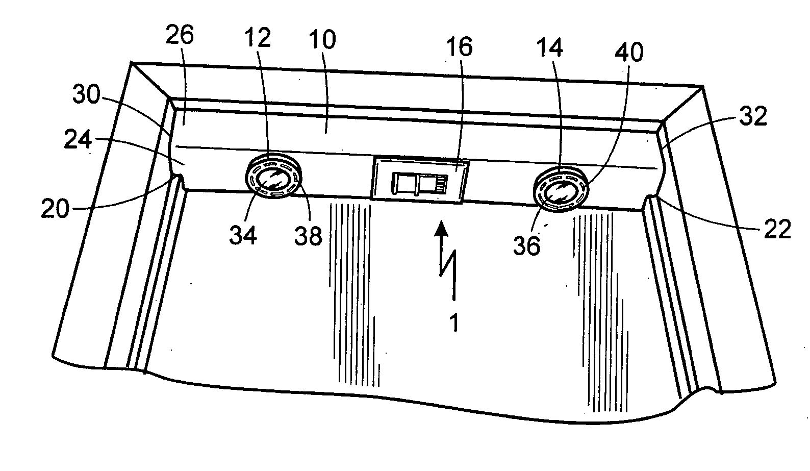
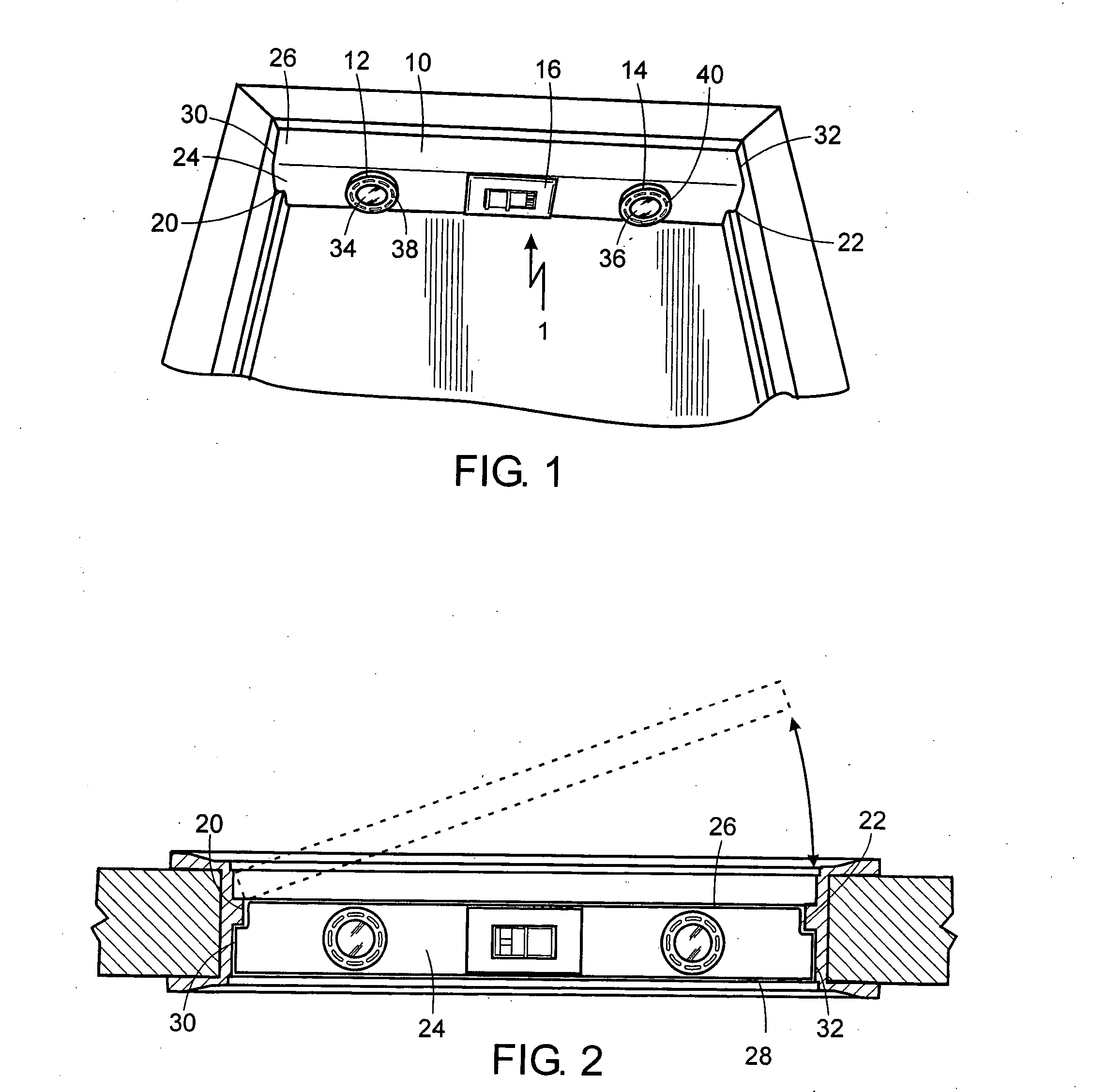
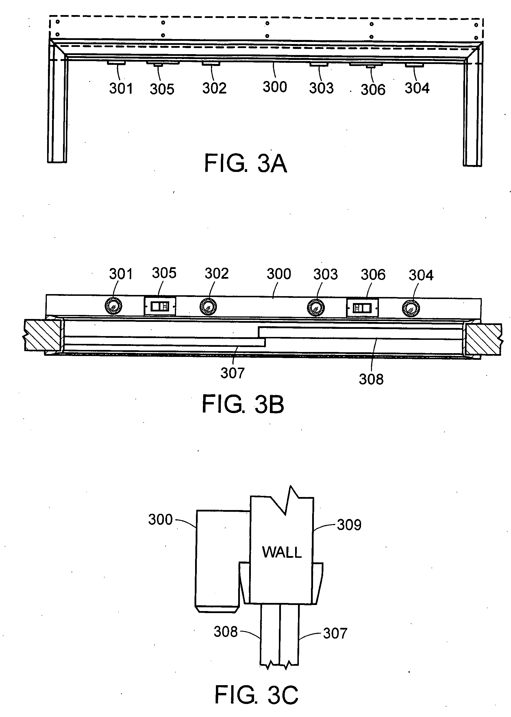
[0014] The following is intended to provide a detailed description of an example of the invention and should not be taken to be limiting of the invention itself. Rather, any number of variations may fall within the scope of the invention, which is defined in the claims following the description.

[0015] Referring now to the drawings, and more particularly to FIGS. 1 and 2, wherein like numbers refer to similar parts, a combination light fixture and motion sensor apparatus 1 is provided in a single enclosure 10 and is shown according to the present invention. Apparatus 1 includes at least one light 12 and at least one motion sensor 16. In the preferred embodiment depicted in FIGS. 1 and 2, apparatus 1 will comprise a pair of lights 12 and 14 and a motion sensor 16 located positioned between lights 12 and 14. In a preferred embodiment having multiple lights, at least one light is mounted on each side of motion sensor 16, as shown in FIG. 1. In an actual embodiment, multiple motion sen...


PUM


Abstract

A combination light fixture and motion sensor apparatus contained in a single enclosure, which turns on automatically when approached and which turns off automatically when the area is vacated, is disclosed. In particular, this apparatus is one that can be mounted in a closet, pantry, cabinet, under a cabinet, or an area where wiring a separate light and switch is not feasible or practicable. The combination light fixture and motion sensor apparatus is contained within a single enclosure, and the apparatus may be mounted inside a closet and above the closet door. By being mounted above the door, the motion from the door being opened triggers the motion sensor so that the light will come on automatically. The apparatus also turns off the light automatically when not needed, so as to save energy.

Description

BACKGROUND OF THE INVENTION [0001] 1. Technical Field [0002] This invention relates generally to light fixtures and lighting controls. More specifically, the present invention is directed to a combination light fixture and motion sensor apparatus. [0003] 2. Description of the Related Art [0004] A conventional closet, particularly as found in older homes, may not have a light fixture of any type in it, which can make it difficult for someone entering the closet to find what they are looking for. Some closets do have a simple light bulb in them that is activated by a pull string or chain. The user must turn off the light when the user leaves the closet by re-pulling on the string. Inventors have over the years tried to find other ways to install or provide a light source in a closet. Generally, installing a light source in a closet involves electrically “hard-wiring” the light into the closet ceiling and a switch into the adjacent wall. Some people who wish to avoid the trouble and ex...

Claims


Application Information

Patent Timeline
Patent Type & Authority Applications(United States)
IPC IPC(8): F21V23/04
CPCF21V23/0442F21V33/0012H05B37/0227Y02B20/40H05B47/13
Inventor ARRUDA, STEVEN S.
Owner ARRUDA STEVEN S
Why Eureka
Try Eureka