This helps you quickly interpret patents by identifying the three key elements:
Problems solved by technology
Method used
Benefits of technology
Benefits of technology
[0006] The present invention overcomes the disadvantages and shortcomings of the prior art discussed above by providing magnetic joints for toy figurines having various configurations that allow for the quick and easy assembly and disassembly of figurine components. In one embodiment of the present invention, the magnetic joint comprises a ball and a pair of sockets magnetically coupled to the ball, wherein the first socket is formed in a first figurine part and the second socket is formed in a second figurine part. Each socket includes a magnet embedde
Problems solved by technology
Existing joint designs suffer from a number of disadvantages.
As such, the user cannot substitute balls of desired colors, patterns, or designs to achieve a desired appearance, nor can the user quickly and conveniently construct figurines using a multitude of interchangeable components.
Moreover
Method used
Image
Click on the blue label to locate the original text in one second.
Reading with bidirectional positioning of images and text.
Examples
Example
DETAILED DESCRIPTION OF THE DRAWINGS
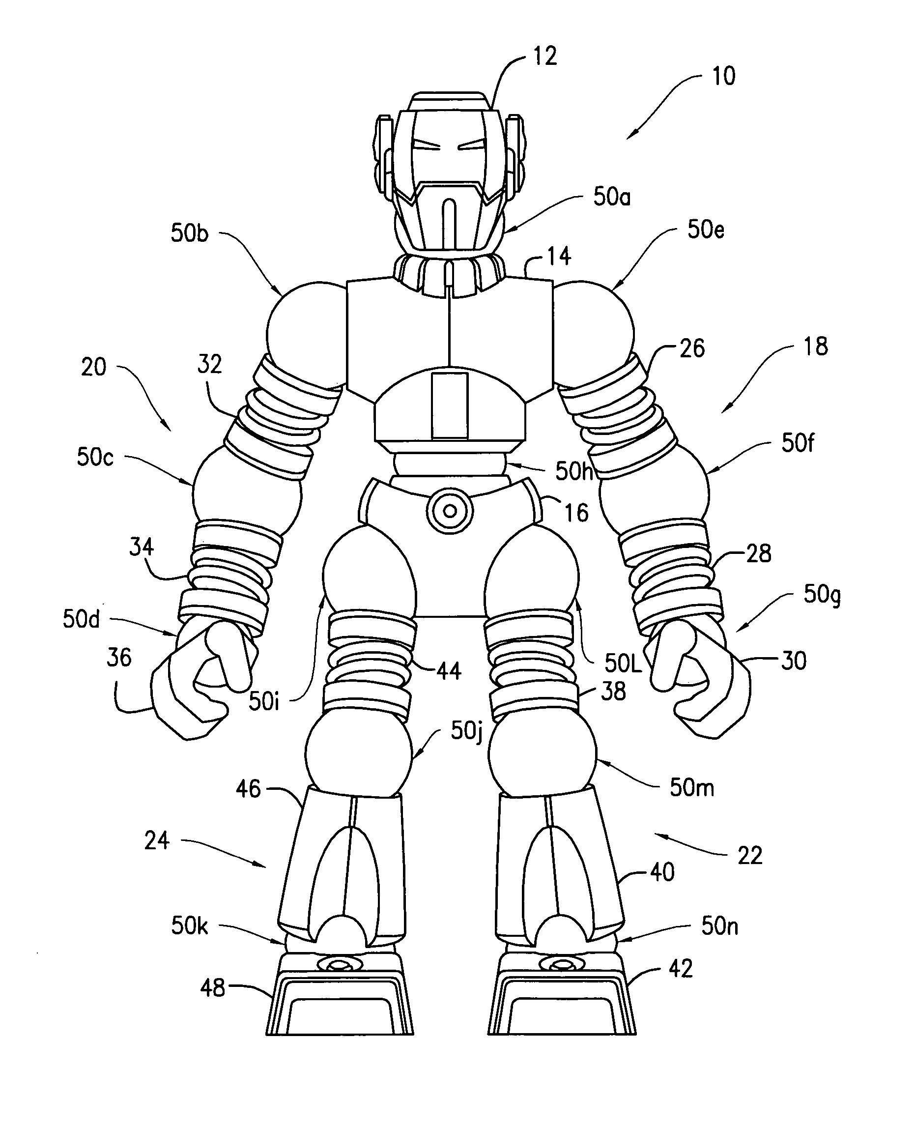
[0030] Referring to FIG. 1, there is shown a toy figurine 10 which includes a head 12, an upper torso 14, a lower torso 16, arms 18, 20, and legs 22, 24. The arm 18 includes a bicep 26, a forearm 28, and a hand 30. Similarly, the arm 20 includes a bicep 32, a forearm 34, and a hand 36. The leg 22 includes a thigh 38, a shin 40, and a foot 42. Similarly, the leg 24 includes a thigh 44, a shin 46, and a foot 48. All of the foregoing parts are movably coupled to their adjoining parts by magnetic joints 50a-n.
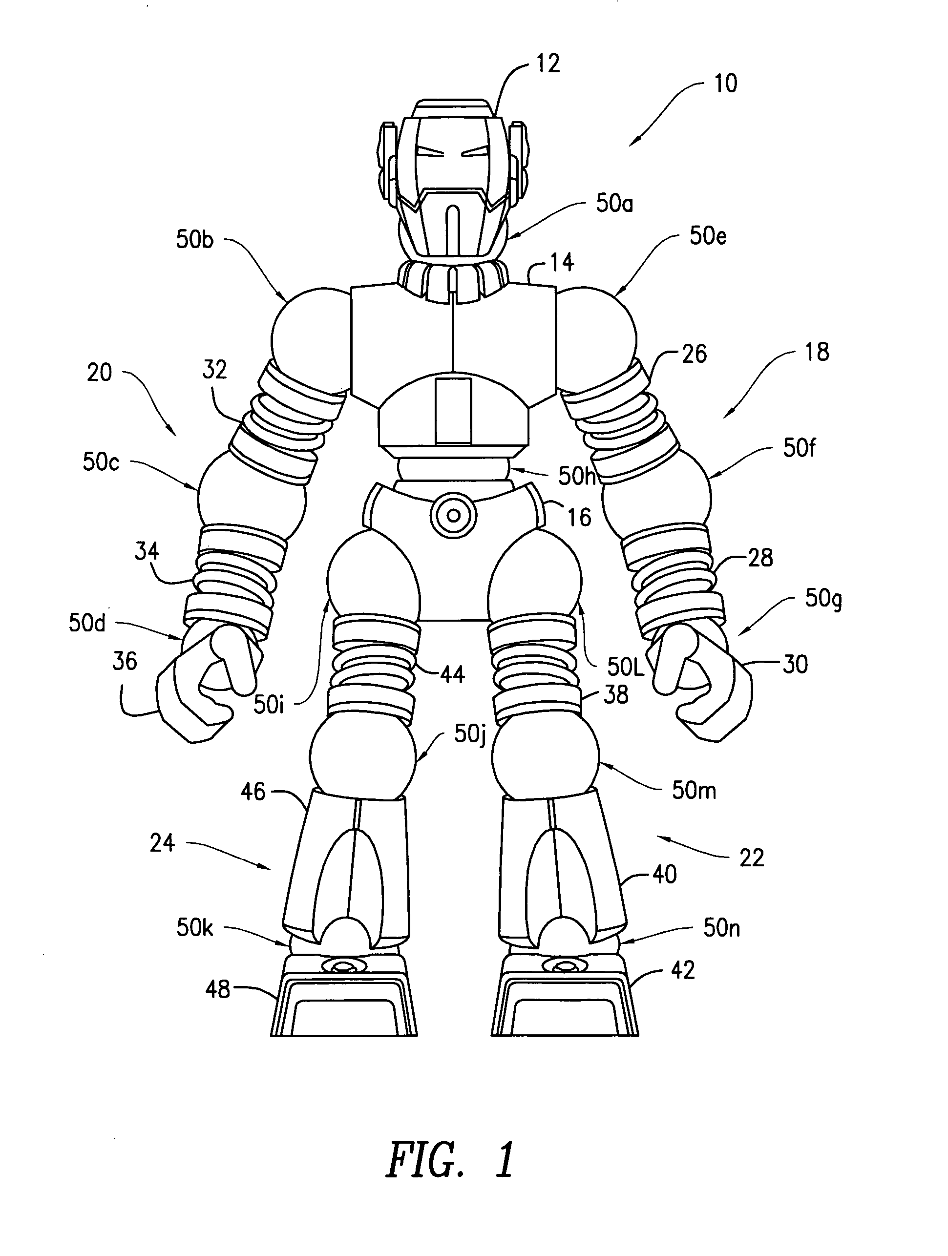
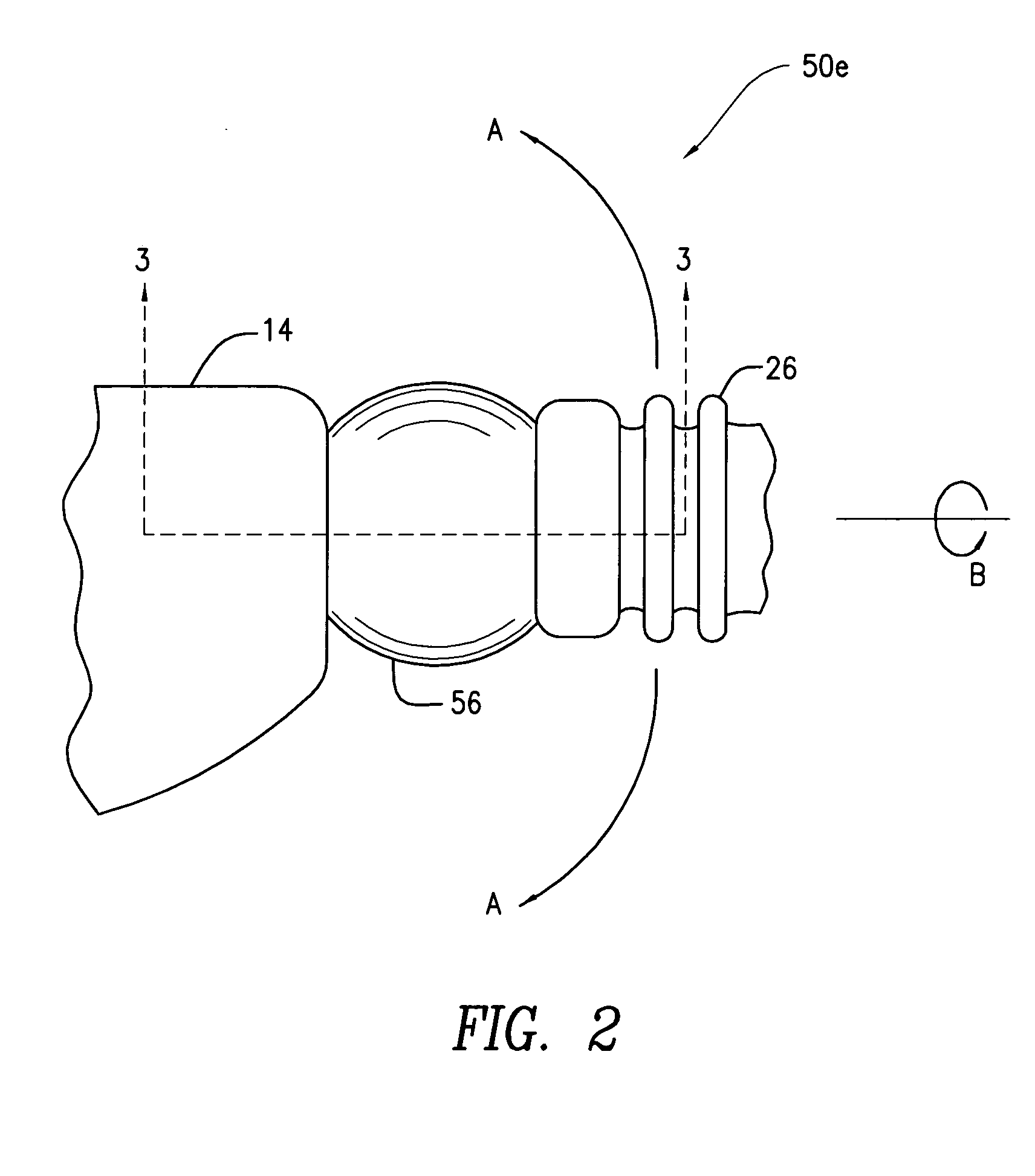
[0031]FIG. 2 is a front elevational view of the magnetic joint 50e shown in FIG. 1, it being understood that each of the magnetic joints 50a-d and 50f-n of FIG. 1 has the same construction as the magnetic joint 50e. With particular reference to FIGS. 2 and 3, a ball 56 is positioned between a pair of magnetic sockets 52a, 52b (see FIG. 3) formed in the upper torso 14 and the bicep 26, respectively. The magnetic joint 50e allows for both angulat...
PUM
Abstract
Magnetic joints for toy figurines are provided. In one embodiment, the joints include a pair of sockets with magnets formed therein and a ball positioned between the sockets, wherein the sockets are magnetically coupled to the ball and allow for rotation and angulation of coupled components. Friction inlays or O-rings could be provided between the ball and the sockets to retain the coupled components in one or more desired positions. In another embodiment, the joints include complementary, generally planar surfaces having magnets embedded therein for coupling the planar surfaces and allowing rotation and indexing of coupled parts. Conductive regions could be provided in the planar surfaces to allow power transmission through the joints. In another embodiment, the joints include a magnetically-coupled peg and socket for providing rotation and indexing of coupled parts.
Description
RELATED APPLICATIONS [0001] This application claims the benefit of U.S. Design patent application Ser. No. 29 / 223,384 filed Feb. 10, 2005; U.S. Design patent application Ser. No. 29 / 223,389 filed Feb. 10, 2005; U.S. Design patent application Ser. No. 29 / 223,385 filed Feb. 10, 2005; U.S. Design patent application Ser. No. 29 / 223,387 filed Feb. 10, 2005; U.S. Design patent application Ser. No. 29 / 223,386 filed Feb. 10, 2005; U.S. Design patent application Ser. No. 29 / 223,383 filed Feb. 10, 2005; U.S. Design patent application Ser. No. 29 / 223,392 filed Feb. 11, 2005; U.S. Design patent application Ser. No. 29 / 223,391 filed Feb. 11, 2005; U.S. Design patent application Ser. No. 29 / 223,397 filed Feb. 11, 2005; U.S. Design patent application Ser. No. 29 / 223,388 filed Feb. 11, 2005; U.S. Design patent application Ser. No. 29 / 223,395 filed Feb. 11, 2005; and U.S. Design patent application Ser. No. 29 / 223,393 filed Feb. 11, 2005, the entire disclosures of which are all expressly incorporated...
Claims
Application Information
Patent Timeline
Application Date:The date an application was filed.
Publication Date:The date a patent or application was officially published.
First Publication Date:The earliest publication date of a patent with the same application number.
Issue Date:Publication date of the patent grant document.
PCT Entry Date:The Entry date of PCT National Phase.
Estimated Expiry Date:The statutory expiry date of a patent right according to the Patent Law, and it is the longest term of protection that the patent right can achieve without the termination of the patent right due to other reasons(Term extension factor has been taken into account ).
Invalid Date:Actual expiry date is based on effective date or publication date of legal transaction data of invalid patent.

