
Radiating member for laminated battery and method of manufacturing the same

a technology of laminated batteries and radiating members, which is applied in the direction of cell components, sustainable manufacturing/processing, and flat cell grouping, etc., can solve the problems of hardly suppressing cell swelling, unable to provide the desired wall contact pressure and cooling properties, and possible difference in the amount of radiated heat between the central zone and the outer peripheral zone of the battery pack, etc. achieve uniform load, effectively radiated, and high load resistance properties

Inactive Publication Date: 2006-08-17
SUBARU CORP +1
View PDF1 Cites 26 Cited by
  • Summary
  • Abstract
  • Description
  • Claims
  • Application Information

AI Technical Summary

Benefits of technology

[0011] The present invention has been made in view of the problems as mentioned above, and it is an object of the invention to provide a radiating member for a laminated cell which is capable of more effectively applying a strong contact pressure to cells, and has improved cooling properties, a battery pack system, and a method of manufacturing the radiating member.

Problems solved by technology

However, the corrugated or triangular spacer is collapsed if a strong contact pressure is applied to the cell, possibly experiencing difficulties in providing a desired wall contact pressure and cooling properties.
Further, this invention cannot rectify the cooling air flowing through the honeycomb metal plates, because they are opposite to each other, so that the air stagnates in a central portion of the battery pack, seemingly resulting in a possible difference in the amount of radiated heat between the central zone and outer peripheral zone of the battery pack.
However, in a laminated cell, the swelling of cells can hardly be suppressed by the laminate film which serves as a sheath.
However, when a large number of cells are contained in a housing as a battery pack, the joints will have volumes occupied thereby too large to be negligible, thus resulting in an increase in the size of the housing.
Thus, the laminated cell has a peculiar problem in the packing into a battery pack.

Method used


Image

  • Radiating member for laminated battery and method of manufacturing the same
  • Radiating member for laminated battery and method of manufacturing the same
  • Radiating member for laminated battery and method of manufacturing the same

Examples


first embodiment

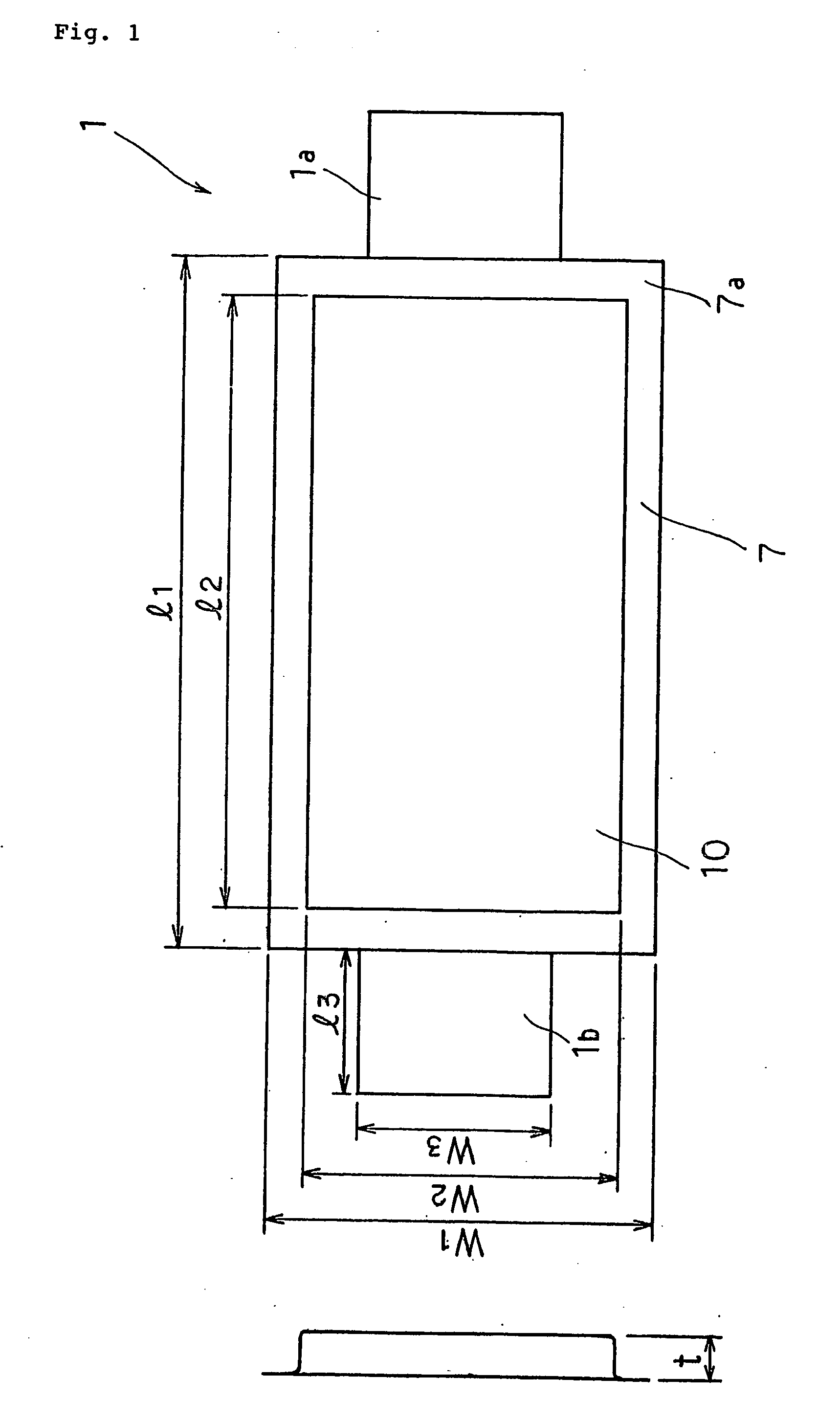
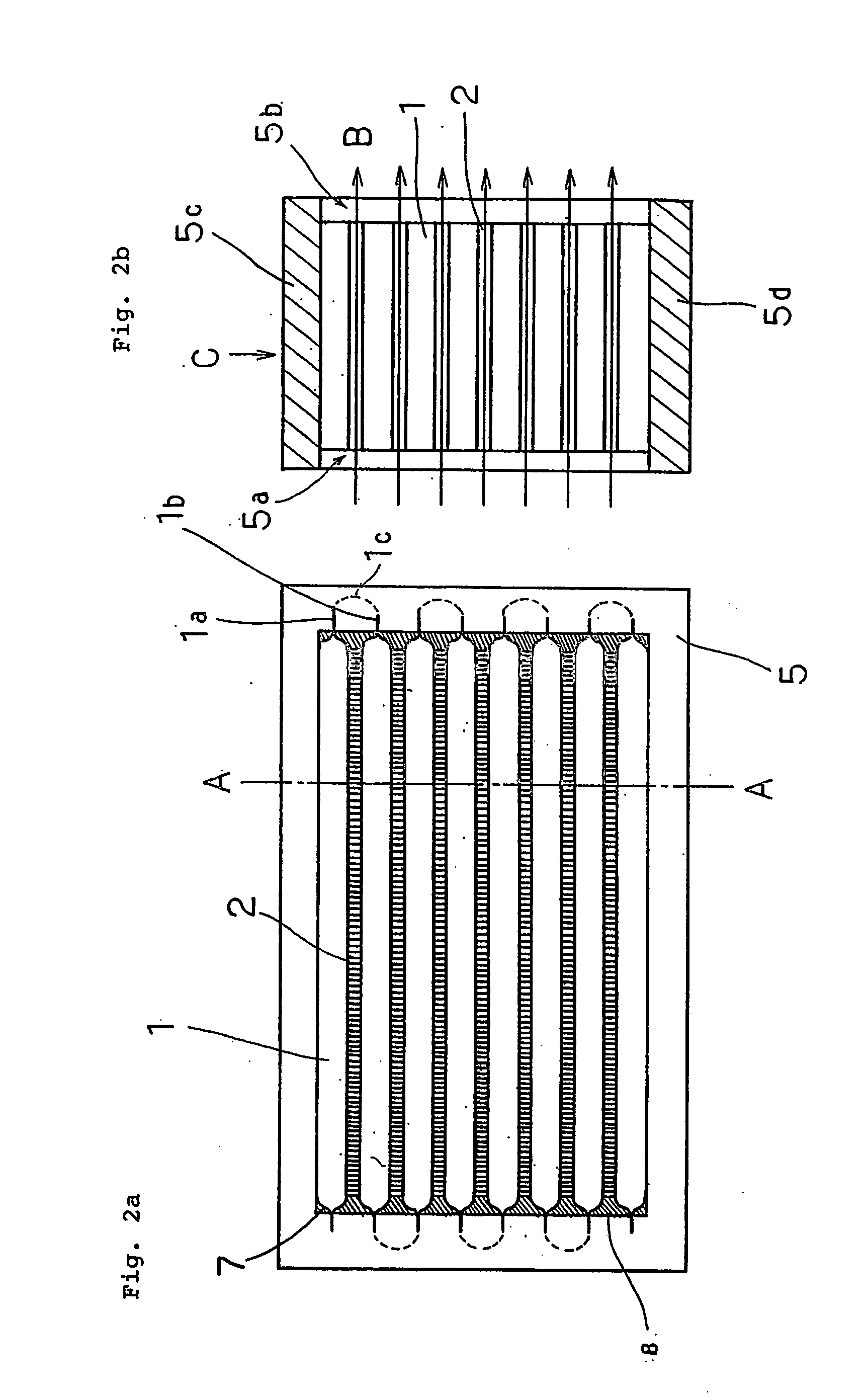
[0039]FIG. 1 illustrates a top plan view and a side view of a laminated cell used in this embodiment. Also, FIG. 2a illustrates a schematic front view of a battery pack of this embodiment, and FIG. 2b illustrates a side sectional view along an A-A line shown in FIG. 2a. Also, FIG. 3a illustrates a front view of a radiating member alone; FIG. 3b a partially enlarged view of the radiating member; and FIG. 3c a lattice-shaped ventilation frame formed by disposing the radiating member in contact with a laminated cell.

[0040] Laminated cell 1 has a structure in which laminated electrode 10 (see FIG. 4) made up of positive pole active electrodes and negative pole active electrodes is hermetically sealed by laminate sheets 7 which are formed by laminating a metal film such as aluminum and a thermally sealable resin film. Specifically, laminated cell 1 is such that laminated electrode 10 is sandwiched by two laminate sheets 7, and laminate sheets 7 are adhered to each other around the perip...

second embodiment

[0053]FIG. 5 schematically illustrates part of a battery pack system of this embodiment. FIG. 5 illustrates only one radiating member and two laminated cells in contact with this radiating member. Also, the structure of the battery pack system of this embodiment is similar to the battery pack system of the first embodiment except that the shape of the radiating member is different from the first embodiment, so that detailed description is omitted.

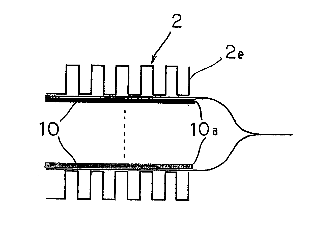
[0054] Radiating member 22 of this embodiment has a length longer than the body of laminated cell 21 except for electrode terminals, and is a preferred configuration when one wishes to increase the amount of radiated heat. This radiating member 22 is roughly divided into two regions, i.e., contact region 22d in contact with laminated cell 21, and non-contact region 22e not in contact with laminated cell 21, where non-contact region 22e is processed to have electric insulating properties. Specifically, non-contact region 22e has been subjec...

third embodiment

[0059]FIG. 6a illustrates a schematic front view of a radiating member of this embodiment, and FIGS. 6b, 6c schematically illustrate part of a battery pack system of this embodiment. FIGS. 6b. 6c each illustrate only one radiating member and two laminated cells in contact with this radiating member. Also, since the structure of the battery pack system of this embodiment is similar to the battery pack system of the first embodiment except that the shape of a radiating member is different from the first embodiment, detailed description is omitted.

[0060] Radiating member 32 of this embodiment has a structure in which radiating member 32a and radiating member 32, the height of which is substantially one-half as compared with radiating member 2 shown in the first and second embodiments, which are stacked one on the other.

[0061] Radiating member 32 illustrated in FIG. 6b is an example in which radiating member 32a made up of first wall 32a1, and second wall 32a2 and third wall 32a3, dis...


PUM

PropertyMeasurementUnit
Timeaaaaaaaaaa
Thicknessaaaaaaaaaa
Thicknessaaaaaaaaaa

Abstract

A radiating member (2) of the present invention comprises a plurality of first wall (2a), and a second wall (2b) connected to the first wall (2a) and formed substantially at right angles to the first wall (2a), which are alternately and continuously formed. The first wall (2a) are arranged substantially perpendicular to the surface (1d) of a laminated cell (1) such that they are not collapsed by loads applied from the top and bottom surfaces of the laminated cells (1). The second wall (2b) make up a flat plane substantially parallel with the surface (1d) in order to gain a heat transfer area and uniformly apply the loads to the laminated cell (1). To ensure a largest possible area for the second wall (2b), R-sections (2c), which connects the second wall (2b) with the first wall (2a), are formed to have a smallest possible radius.

Description

TECHNICAL FIELD [0001] The present invention relates to a radiating member for a laminated cell covered with a laminate material, a battery pack system, and a method of manufacturing the radiating member. BACKGROUND ART [0002] At present, batteries used in compact electronic devices such as portable information communications devices such as portable telephones and notebook-type personal computers, video cameras, and card-shaped electronic calculators, which attach importance to the portability, are required to be light and thin. Also, as requests are increased for a reduction in resources and energy for purposes of international protection for the earth environment, the development is rapidly under progress for electric cars and hybrid electric cars (hereinafter simply called the “electric cars”) which are mounted with batteries for driving motors. The batteries mounted in the electric cars are also required to be light and thin, as a matter of course, in order to improve the drivi...

Claims


Application Information

Patent Timeline
IPC IPC(8): H01M10/50H01M6/46B26D7/06B21D43/28H01M10/04B21D53/02F28D1/00H01M10/60H01M10/613H01M10/625H01M10/647H01M10/6551H01M10/6557H01M10/6562H01M10/6563H01M10/6566H01M50/105
CPCF28F3/025Y10T29/4935H01M2/0287H01M2/348H01M10/0436H01M10/4207H01M10/5004H01M10/5016H01M10/5032H01M10/5059H01M10/5063H01M10/5065H01M10/5067Y10T29/49108H01M2/0207H01M10/625H01M10/6563H01M10/647H01M10/6557H01M10/6561H01M10/613H01M10/6562Y10T83/0448Y02E60/10H01M50/124H01M50/581Y02P70/50H01M50/105H01M10/6551
Inventor KANAI, TAKESHI
Owner SUBARU CORP
Learn More