Deployment of applications in a multitier compute infrastructure

Active Publication Date: 2006-08-17
COLLATION +1
View PDF34 Cites 137 Cited by
  • Summary
  • Abstract
  • Description
  • Claims
  • Application Information

AI Technical Summary

Benefits of technology

[0107] In one approach, there is a one-to-one correspondence between agents 1040 and tasks. One advantage of this approach is its modularity. New tasks can be implemented by adding new agents. Existing tasks can be updated simply by modifying the corresponding agent. The agent manager 1080 facilitates the process of adding, removing and/or updating agents 1

Problems solved by technology

One drawback of the multitier and software component approaches is that, typically, many components are used in order to implement the desired functionality.
Cross-tier relationships, such as those linking the web server, DNS server and access router with each other, can be more complex but these often are the relationships that have a direct bearing on the availability, performance and security of the overall application.
Due to this increased complexity, managing a multitier compute infrastructure and the applications implemented on the infrastructure is more difficult.
Tasks such as installing, configuring, activating, updating and monitoring enterprise functions are more complex compared to a situation where a monolithic piece of code executes on a single computer in a fixed network location.
In the meantime, it is increasingly more difficult to manage the application and its updates, including for example the tasks of merely installing and correctly configuring the updates.
Enterprise management capability has not kept pace with the shorter development cycle.
However, as the scope of enterprise applications expands and the different tiers become more distributed, the likelihood of uncovering all issues and of successfully deploying an application on the first try decreases.
But troubleshooting can be time-consuming as th

Method used


Image

  • Deployment of applications in a multitier compute infrastructure
  • Deployment of applications in a multitier compute infrastructure
  • Deployment of applications in a multitier compute infrastructure

Examples


Embodiment Construction

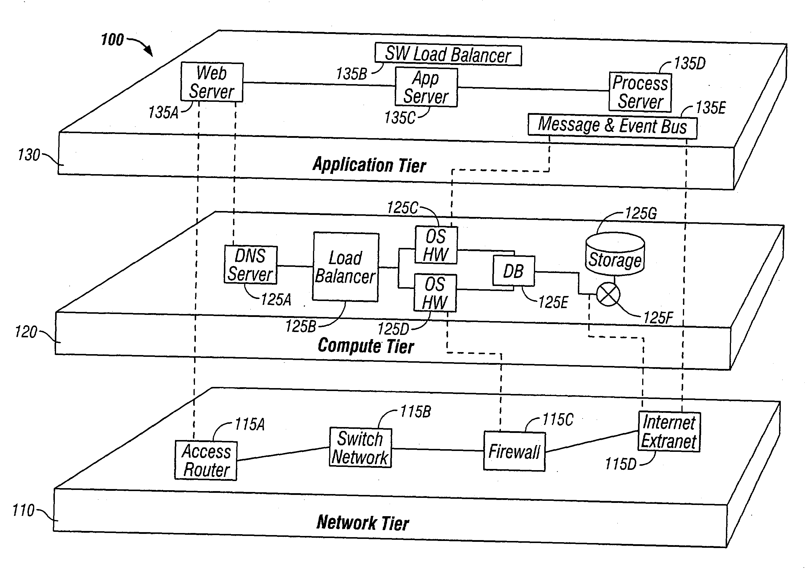
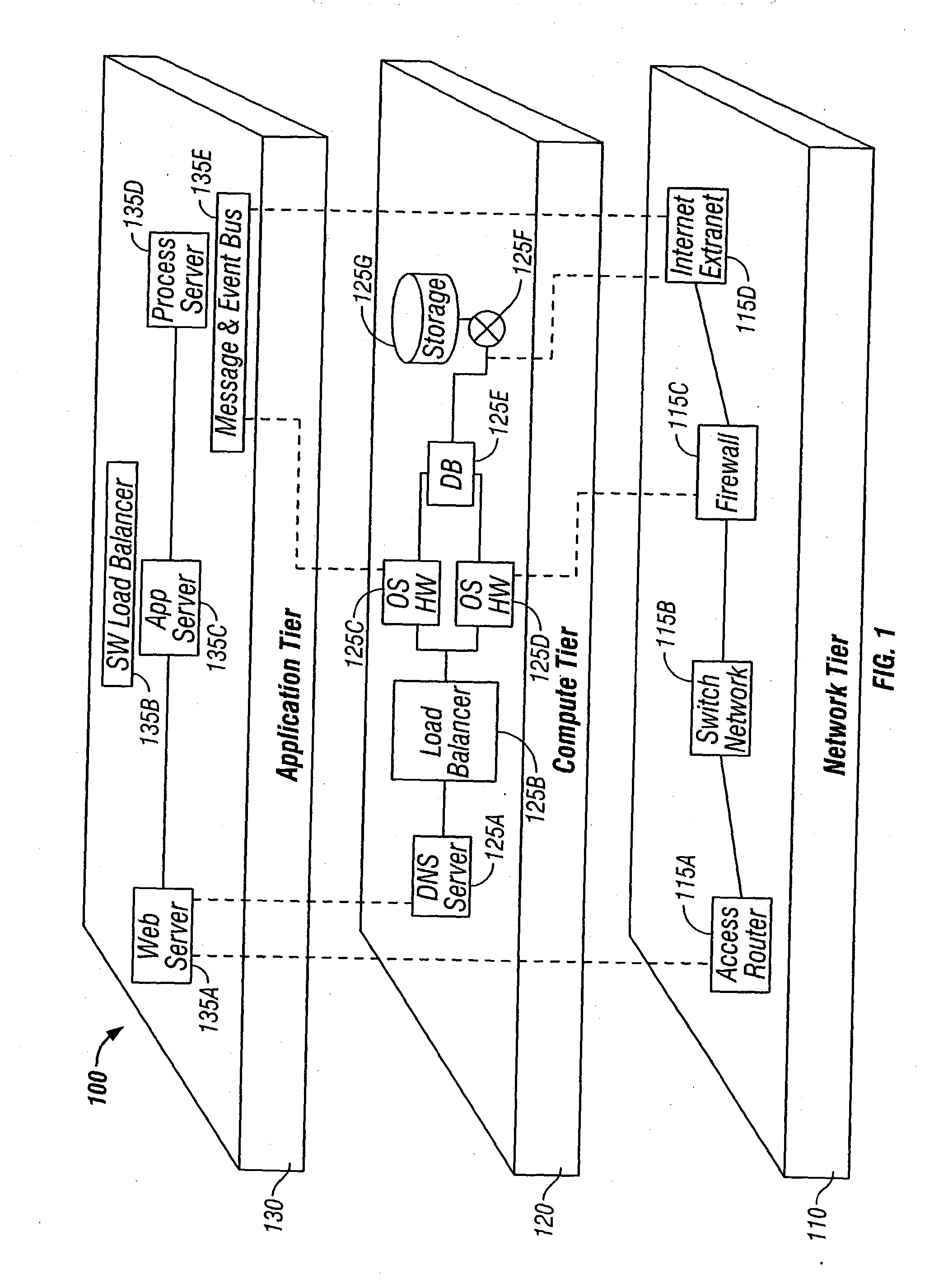
[0032]FIG. 1 is a representation of an example multitier compute infrastructure 100. The infrastructure 100 includes multiple tiers 110, 120, 130 of components 115, 125, 135, which are interconnected to provide overall functionality. Generally speaking, the different tiers function at different “levels” and preferably function somewhat independently of each other. In one approach, each tier performs certain functions and there is a standardized interface between the tiers. The “interface” between the tiers may actually consist of a collection of standardized interfaces between individual components. In this way, individual tiers / components can be modified without affecting the other tiers / components so long as the interfaces are maintained. This provides flexibility and modularity. It also allows each tier to be optimized for its specific tasks. However, as a result of this, the tiers and the components can also be vastly different.

[0033] In the example shown in FIG. 1, the multiti...


PUM


Abstract

An application model automates deployment of an application. In one embodiment, the application model includes a static description of the application and a run-time description of the application. Deployment phases, such as installation, configuration and activation of the application are executed according to the application model.

Description

CROSS-REFERENCE TO RELATED APPLICATIONS [0001] This application claims priority under 35 U.S.C. §119(e) to U.S. Provisional Patent Application Ser. No. 60 / 396,666, “Operational Automation Platform for Component Architectures,” by Casier Johan et al., filed Jul. 17, 2002. This application relates to U.S. patent application Ser. No. ______, “Topology Mapping of a Multitier Compute Infrastructure,” by Or et al., filed Feb. 11, 2003. The subject matter of the foregoing is incorporated herein by reference in its entirety.BACKGROUND OF THE INVENTION [0002] 1. Field of the Invention [0003] This invention relates generally to the deployment of applications in a multitier compute infrastructure, including those that host multitier applications. In a specific embodiment, it relates to the deployment of multitier applications that are based on a software component architecture, for example the Java 2 Platform, Enterprise Edition (J2EE) or NET. [0004] 2. Description of the Related Art [0005] Wi...

Claims


Application Information

Patent Timeline
IPC IPC(8): G06F9/44G06F9/445
CPCG06F8/61
Inventor OR, YANCASIER, JOHANGARIMELLA, KRISHNABELLUR, UMESHKOPER, JOHNJOSHI, SHASHANKSUNDARESAN, VINU
Owner COLLATION
Why Eureka
Try Eureka