Flame simulating assembly including an air filter

a technology of simulating assembly and air filter, which is applied in the direction of combustion process, combustion ignition, heating fuel, etc., can solve the problem of least partial obstruction of air filter

Inactive Publication Date: 2006-08-24
DIMPLEX NORTH AMERICA
View PDF85 Cites 44 Cited by
  • Summary
  • Abstract
  • Description
  • Claims
  • Application Information

AI Technical Summary

Benefits of technology

[0019] In yet another aspect, the invention includes one or more electric lamps, and a control device operatively connected to the lamp(s) for activating and de-activating the lamp(s). The control device includes one or more sensors for sensing a temperature of the air in the air flow. The invention also includes a control circuit operatively connecting the sensor to the lamp for activating the lamp when the temperature of the air is at a predetermined temperature or higher. The sensor is positioned proximal to the heating element so that when the air filter is obstructed to a predetermined extent, the lamp is energized, indicating that the air filter is due for replacement.

Problems solved by technology

The increase in the temperature of the air surrounding the thermal switch up to the predetermined temperature (and beyond) results from at least partial obstruction of the air filter.

Method used


Image

  • Flame simulating assembly including an air filter
  • Flame simulating assembly including an air filter
  • Flame simulating assembly including an air filter

Examples


Embodiment Construction

)

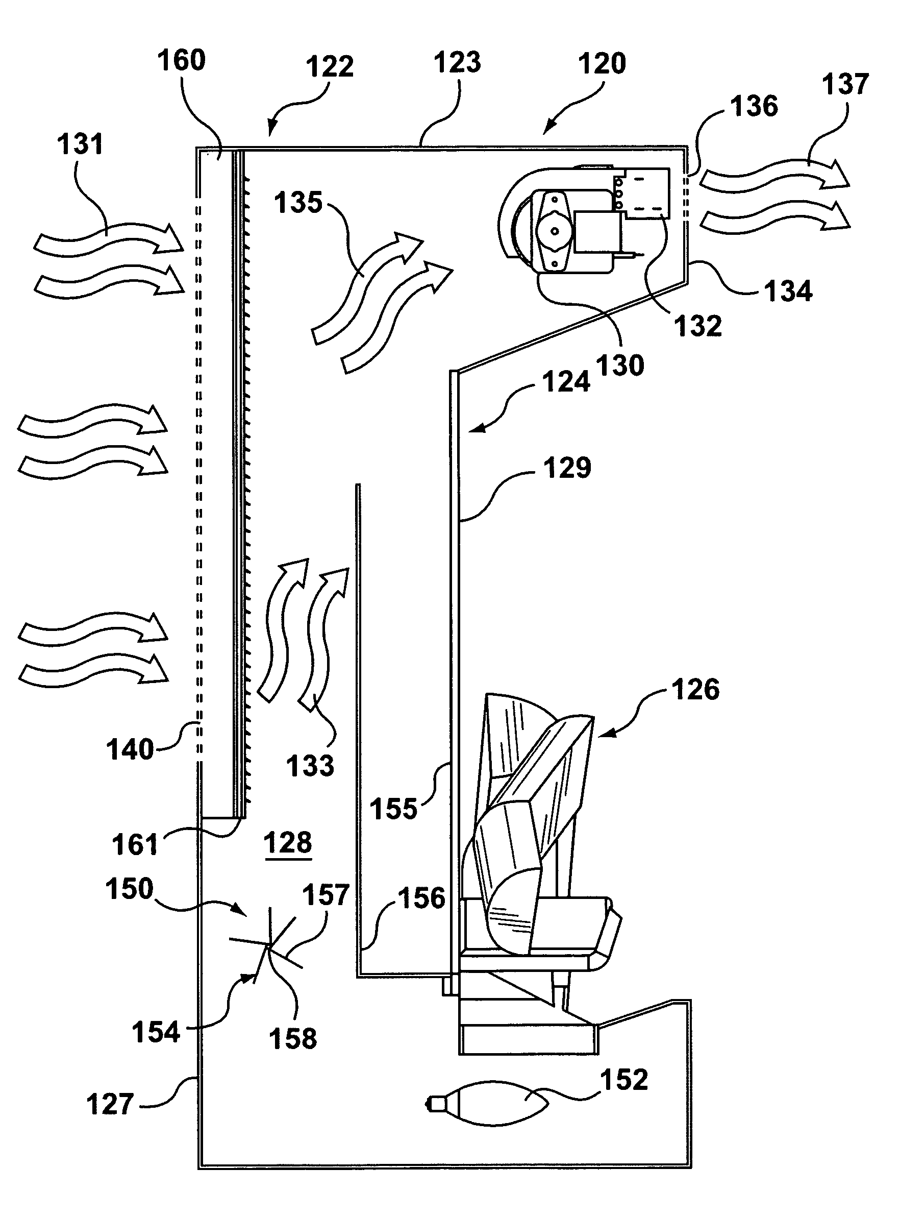
[0039] Reference is first made to FIGS. 3-5 to describe a preferred embodiment of a flame simulating assembly in accordance with the invention indicated generally by the numeral 120. The flame simulating assembly 120 preferably includes a housing 122 with a top panel 123, two or more side panels 125 supporting the top panel 123, a back panel 127 connecting the side panels 125, and one or more front panels 134 positioned substantially opposite to the back panel 127. As can be seen in FIGS. 3 and 4, the flame simulating assembly also includes a simulated fuel bed 126 disposed in the housing 122 and a screen 124 positioned behind the simulated fuel bed 126, and the screen 124 has a front surface 129 disposed adjacent to the simulated fuel bed. The flame simulating assembly 120 additionally includes a flame image subassembly 150 for providing images of flames on the front surface 129 of the screen 124, as will be described. As can be seen in FIG. 3, the screen 124, the housing 122 and ...


PUM


Abstract

A flame simulating assembly having a housing including a top panel, two or more side panels supporting the top panel, a back panel connecting the side panels, and one or more front panels positioned substantially opposite to the back panel. Also, the assembly has a simulated fuel bed, a screen positioned behind the simulated fuel bed, and a flame image subassembly for providing images of flames on the screen, and the screen, the housing and the simulated fuel bed define an internal chamber. The assembly also has a fan positioned to provide an air flow through the chamber from one or more intake apertures to one or more exit apertures, through which said air exits the chamber, and one or more filters for filtering at least a portion of said air in the air flow. The internal chamber is substantially airtight, except for the intake and exit apertures.

Description

FIELD OF THE INVENTION [0001] This invention is related to flame simulating assemblies. BACKGROUND OF THE INVENTION [0002] Various types of flame simulating assemblies are known. One type of known flame simulating assembly (shown in FIGS. 1 and 2) typically includes a simulated fuel bed, one or more light sources, a screen disposed behind the simulated fuel bed for diffusing and transmitting light from the light source, and a flicker element for causing light from the light source to fluctuate, or flicker, to simulate flames. Images of flames are provided by fluctuating light from the light source which is transmitted through the screen. Typically, the known electric flame simulating assembly also includes a flames effect element winch configures fluctuating light from the light source to form the images of flames which are transmitted through the screen. An example of this type of flame simulating assembly is disclosed in U.S. Pat. No. 5,642,580 (Hess et al.). [0003] In another typ...

Claims


Application Information

Patent Timeline
Patent Type & Authority Applications(United States)
IPC IPC(8): F24B1/191
CPCF24B1/1808F24C7/004
Inventor HESS, KRISTOFFERSTINSON, KELLY
Owner DIMPLEX NORTH AMERICA
Why Eureka
Try Eureka