
Surgical instrument with trigger control

a surgical instrument and trigger control technology, applied in the field of medical devices, can solve the problems of compromising stability, affecting the function of the instrument, and troublesome use of surgical instruments with this bent handle design,

Inactive Publication Date: 2006-08-24
SHORTI RAMI
View PDF76 Cites 177 Cited by
  • Summary
  • Abstract
  • Description
  • Claims
  • Application Information

AI Technical Summary

Benefits of technology

[0008] The present invention may be described as a surgical device comprising an ergonomic handle having a finger actuator configured to receive a single finger of a user to control an attached, elongated tubular portion extending from the ergonomic handle. The elongated tubular portion may have a longitudinal axis, and the finger actuator may be positioned substantially in line with the longitudinal axis of the tubular portion. Furthermore, the surgical device may also include a rod functionally disposed within the tubular portion along the longitudinal axis. The rod may be coupled proximally to the finger act...

Problems solved by technology

Surgical instruments with this bent-handle design can be troublesome to use.
Additionally, the bent-handle design does not efficiently translate force from the handle to the functional end of the instrument.
This undesirable movement may be translated along the instrument to the functional end, thus compromising stability.

Method used


Image

  • Surgical instrument with trigger control
  • Surgical instrument with trigger control
  • Surgical instrument with trigger control

Examples


Embodiment Construction

[0017] Reference will now be made to the exemplary embodiments illustrated in the drawings, and specific language will be used herein to describe the same. It will nevertheless be understood that no limitation of the scope of the invention is thereby intended. Alterations and further modifications of the inventive features illustrated herein, and additional applications of the principles of the inventions as illustrated herein, which would occur to one skilled in the relevant art and having possession of this disclosure, are to be considered within the scope of the invention.

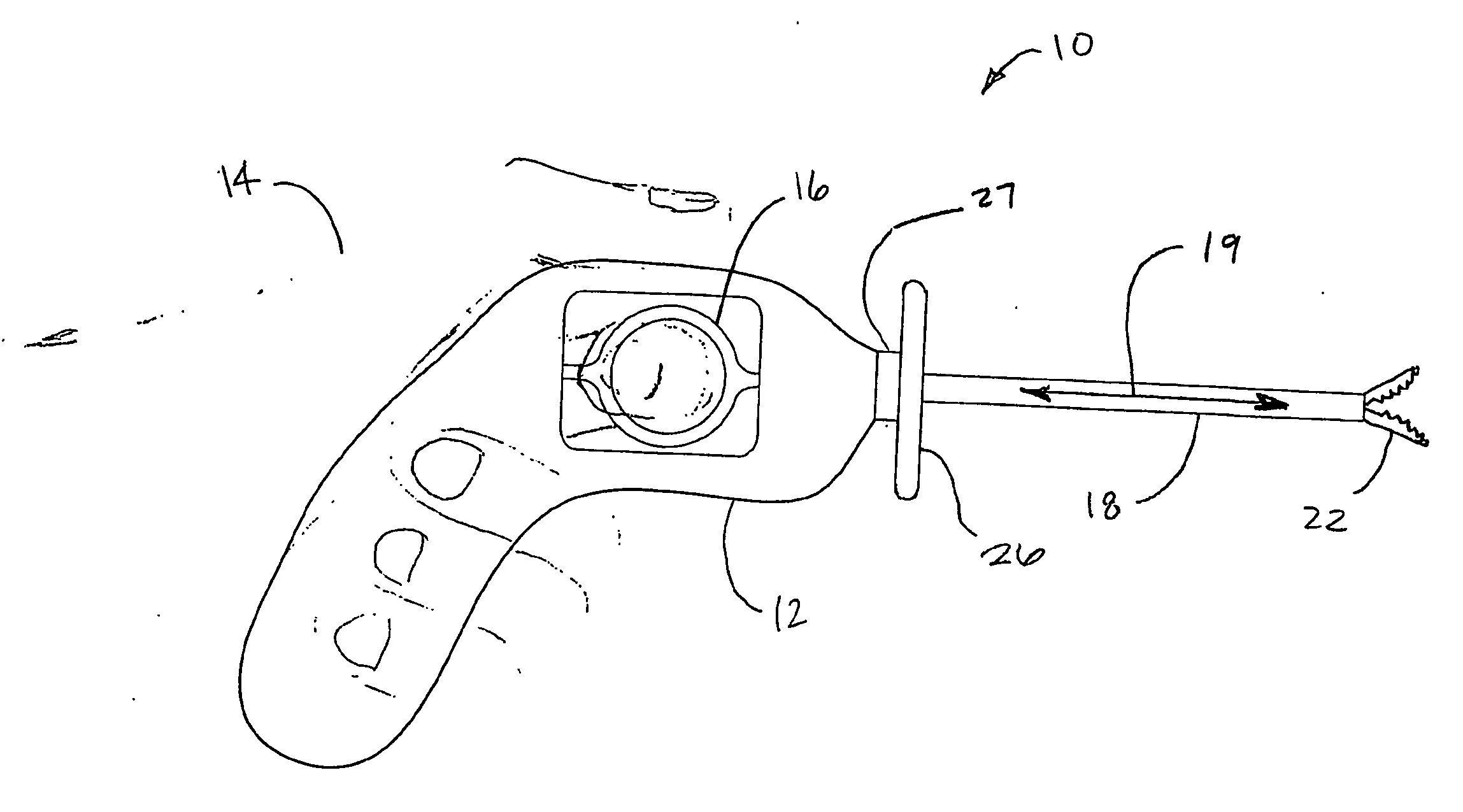
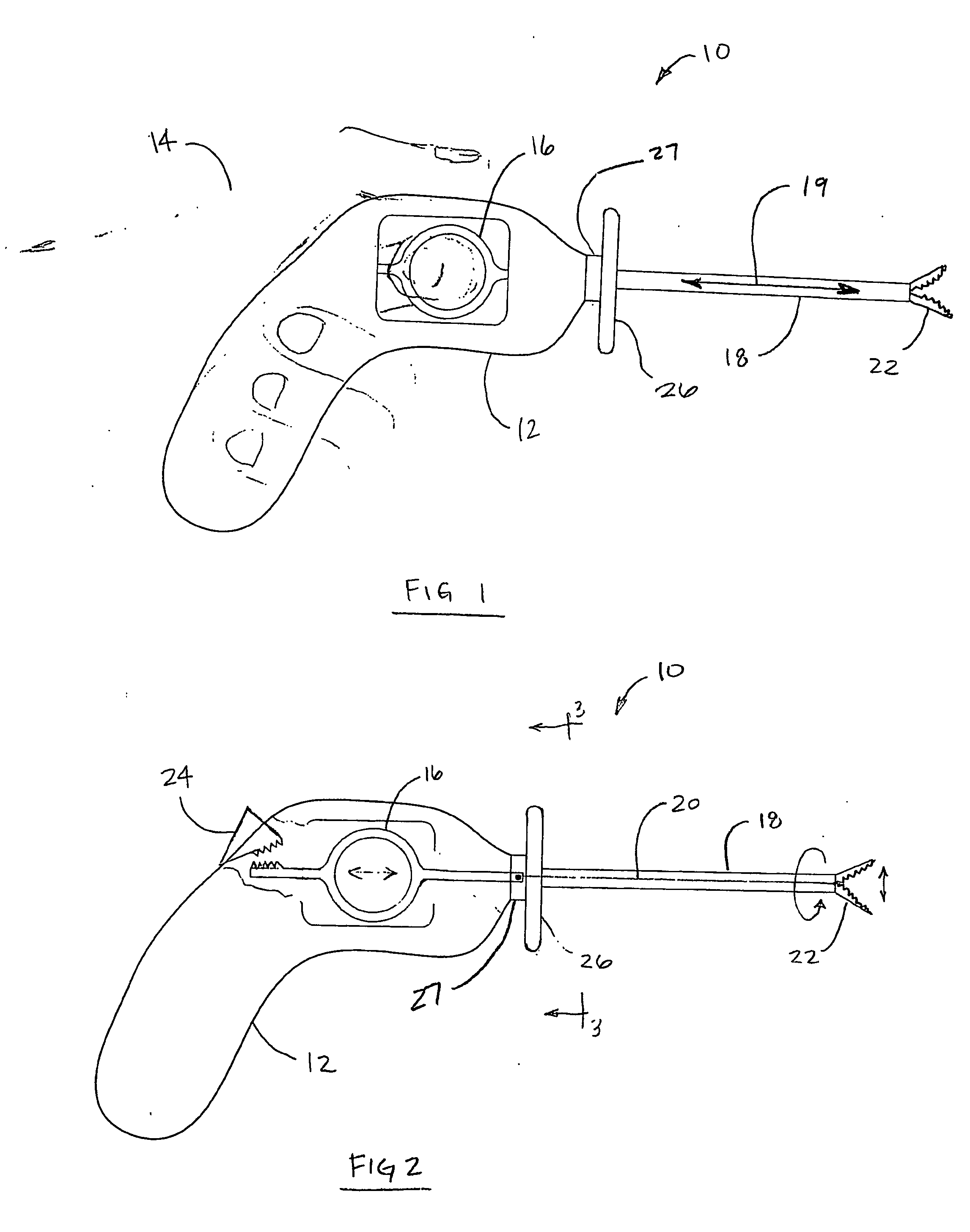
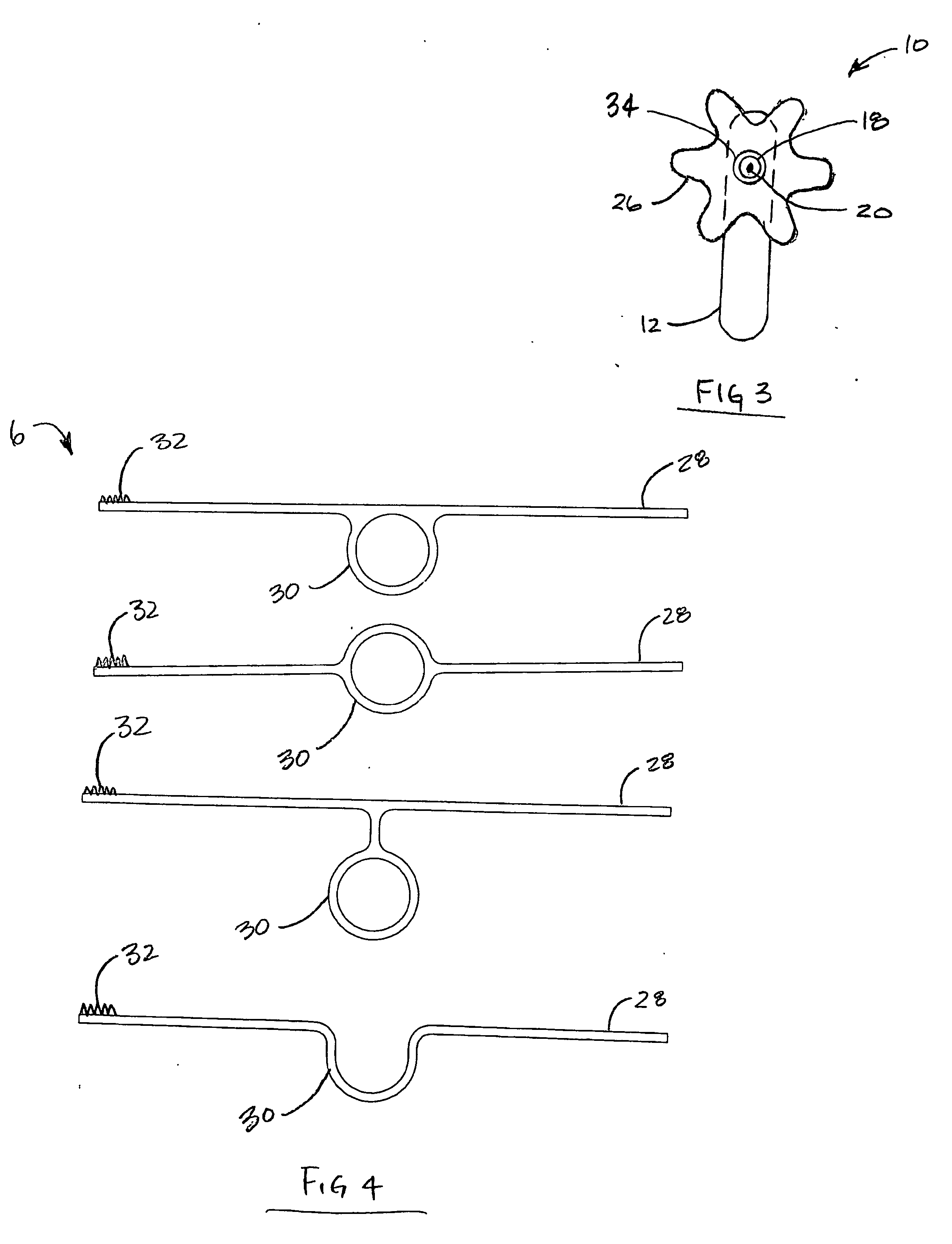
[0018] The present invention may be embodied as a surgical device as shown in FIG. 1 and FIG. 2. The surgical device 10 may have an ergonomic handle 12, shaped to conform to a user's hand 14 held in a relaxed functional position, thus reducing hand and wrist strain that ultimately leads to Carpal Tunnel Syndrome and chronic joint stress. The ergonomic handle may be in the shape of a pistol grip, or any other sh...


PUM


Abstract

A surgical device 10 with an ergonomic handle 12 and, an elongated tubular portion 18 extending from the ergonomic handle 12 to a functional end 22. The elongated tubular portion 18 has a longitudinal axis 19, and a finger actuator 16 is positioned substantially in line with this axis. Furthermore, the surgical device 10 may also include a rod 20 functionally disposed within the tubular portion 18 along the longitudinal axis 19. The rod 20 may be coupled proximally to the finger actuator 16 and distally to the functional end 22, such that bidirectional pressure applied by the user's finger to the finger actuator 16 along the longitudinal axis 19 manipulates the functional end 22 in a bidirectional manner in response to or in a common direction to the bidirectional pressure. The surgical device 10 may further comprise a ratcheting mechanism 24 to lock the finger actuator 16 in a fixed position, thus locking the functional end 22 in a fixed position. Additionally, the functional end 22 may be free to rotate around the longitudinal axis 19, and the elongated tubular portion 18 may be detachable from the ergonomic handle 12.

Description

BACKGROUND OF THE INVENTION [0001] 1. Field of Invention [0002] The present invention relates generally to medical devices. More particularly, the present invention relates to trigger controlled surgical instruments. [0003] 2. Description of Prior Art [0004] Handles for surgical instruments have traditionally been based on a paradigm of design that is decades old, a design that was adopted to facilitate their use in upper airway endoscopy. These instruments are bent such that their handles are as much as 90 degrees out of alignment with their functional ends. The original design was required to allow a user to have a direct line of vision down a sheath into the area where the surgery is performed. With the advent of fiber optics, the requirements for the bent handle design were eliminated. Surgeons today manipulate surgical instruments by means of a video screen, not a direct line of vision down a sheath. Given this change in technology regarding the visual aspects of surgery, it is...

Claims


Application Information

Patent Timeline
IPC IPC(8): A61B17/28A61BA61B17/00A61B19/00
CPCA61B17/29A61B17/2909A61B2017/00424A61B2017/00438A61B2017/00464A61B2017/291A61B2017/2911A61B2017/2924A61B2017/2925A61B2017/2929A61B2017/2946A61B2019/4868A61B2090/0813
Inventor DOWNEY, EARL C.
Owner SHORTI RAMI
Learn More