Surgical instrument

Inactive Publication Date: 2006-08-24
HITACHI LTD
View PDF6 Cites 405 Cited by
  • Summary
  • Abstract
  • Description
  • Claims
  • Application Information

AI Technical Summary

Benefits of technology

[0010] According to the invention, a position and a posture of a gripper, which functions as a forceps, can be easily and stably operated by an operator movements without strain at an operating part without the use of electronic control such as an actuator, etc.
[0011] Since a position a

Problems solved by technology

With the related art disclosed in JP-A-2001-276091, however, a complicated control of rotary operations of first and second rotating shafts provided on the joints must be exercised by operation of the joy stick and driving of the motor since the joy st

Method used


Image

  • Surgical instrument
  • Surgical instrument
  • Surgical instrument

Examples


Embodiment Construction

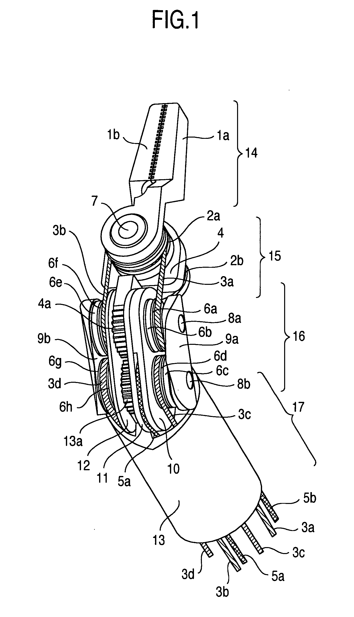
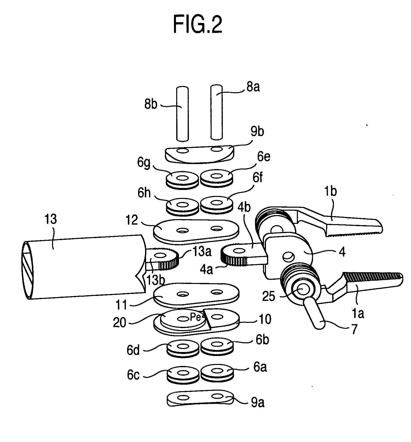
[0031] A surgical instrument according to the invention will be described with reference to FIGS. 1 to 4.

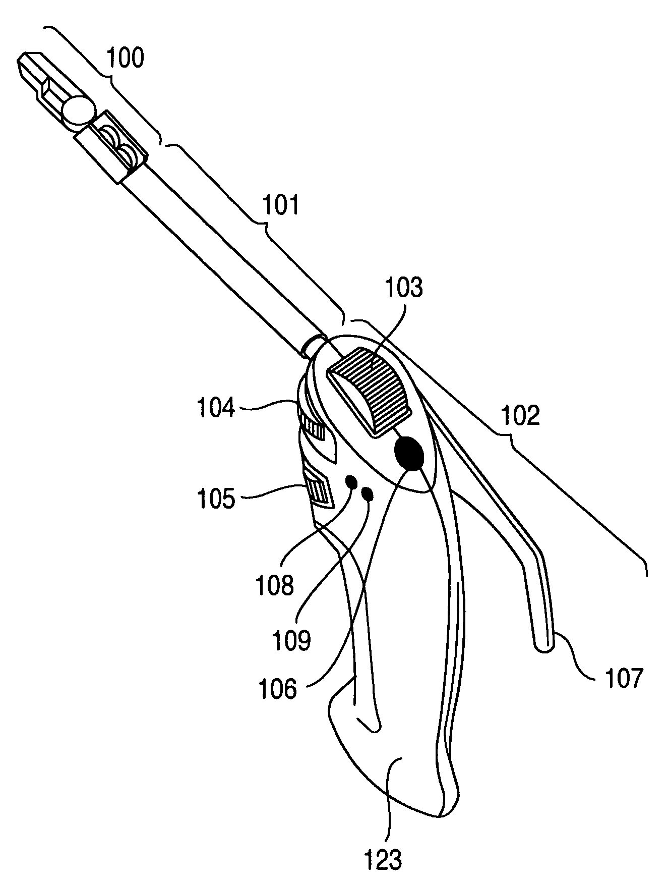
[0032] A surgical instrument for medical care will be exemplarily described for the purpose of a specific illustration (the invention is not specifically limited to a surgical instrument for medical care but provides a construction for general operation tools, a gripper of which is manually operated). A tip end portion (also, referred below to as a tip end joint or an instrument joint) of a surgical instrument (also, referred below to as instrument) comprises a gripper (forceps part) 14 that grips a suture thread, a needle, or the like, a tip end part 15 positioned near a lower portion of the gripper 14 shown in FIG. 1, an intermediate part 16 that forms a second joint together with the tip end part 15, a root part 17 that forms a first joint together with the intermediate part 16, and drive wires 3a to 3d, 5a, 5b for operation of the gripper 14, the tip end part 15, and the int...


PUM


Abstract

A surgical instrument comprising a tip end joint part having an openable and closeable gripper, an operating part including a hand grip and a plurality of operating dials, and an arm part that accommodates a wire for cooperation of actions of the operating part and the tip end joint part. A first operating dial is arranged above the hand grip and on an upper inclined surface of the operating part, second and third operating dials are arranged above the hand grip and on a front surface of the operating part, the first operating dial is operated by a thumb and the second operating dial is operated by a forefinger whereby the tip end joint part is operated vertically and operated laterally to perform a swinging action, and the third operating dial is operated by a forefinger whereby the tip end gripper is operated to open and close.

Description

BACKGROUND OF THE INVENTION [0001] The present invention relates to a surgical instrument to be used in a clinical site, and more particular, to a surgical instrument, of which a position and a posture can be operated by a wire drive type joint. [0002] As a related art for a medical manipulator, which includes movable parts of two degrees of freedom at a tip end of a forceps and a forceps operating part at a rear end of the forceps to minutely operate a forceps, JP-A-2001-276091 discloses an arrangement, which comprises at a tip end of a forceps a first rotary joint and a second rotary joint, and in which a motor at an operating part drives to control the respective joints through gears, etc. to perform an operation of determining a posture of a tip end of the forceps, and a lever provided on an operating rod is operated to control an amount of opening and closing of the forceps. [0003] JP-A-2004-154164 discloses a related art of a multiple degree-of-freedom type treatment tool incl...

Claims


Application Information

Patent Timeline
IPC IPC(8): A61B17/28
CPCA61B17/29A61B17/2909A61B19/22A61B2017/00424A61B2017/2902A61B2017/292A61B2017/2923A61B2017/2927A61B2017/2929A61B2017/2932A61B2019/2242A61B34/70A61B34/71
Inventor NISHIZAWA, KOUJIHOSHINO, TAKESHIMARUYAMA, YUKINOBU
Owner HITACHI LTD
Why Eureka
Try Eureka