Vehicle shift module assembly

Active Publication Date: 2010-02-11
ADMIRAL TOOL & MFG OF MICHIGAN
View PDF5 Cites 4 Cited by
  • Summary
  • Abstract
  • Description
  • Claims
  • Application Information

AI Technical Summary

Benefits of technology

[0004]The present invention provides a safety solenoid shaft positive interlock mounted directly adjacent a shift module swing arm that maintains a vehicle shift lever in the park position until the brake pedal is depressed. At the same time, the shift module assembly is simple in construction and operation, and requires little or no maintenance.
[0005]A mounting bracket allows the shift module assembly and its solenoid locking mechanism to be mounted directly to the steering column of the vehicle as an integral compact unit. The shift module assembly allows regular operator manual shifting between park, drive, reverse, and neutral, and communicates the operator's request to the vehicle's transmission through a bishop head pin attached to a transmission shift control rod. The shift module assembly includes a solenoid armature shaft movable to a position in contact with a swing arm of the shift module assembly, precluding movement of the shifting lever out of the park pos

Problems solved by technology

Often times, these safety mechanisms are overly complicated aid require many electronic and mechanical moving parts.
It is also difficult to incorporate these safety mechanisms into existing modular and compact vehicle components.
This creates a problem because of the tendency for overly complicated and widely dispersed mechanical parts that require maintenance or fail completely.
However, presently available devices do not deploy a control mechanism attached directly to the shift module that applies a positive mechanical stop mechanism against the shift swing arm, thus physically preventing movement of the swing arm out of the park positi

Method used


Image

  • Vehicle shift module assembly
  • Vehicle shift module assembly
  • Vehicle shift module assembly

Examples


Embodiment Construction

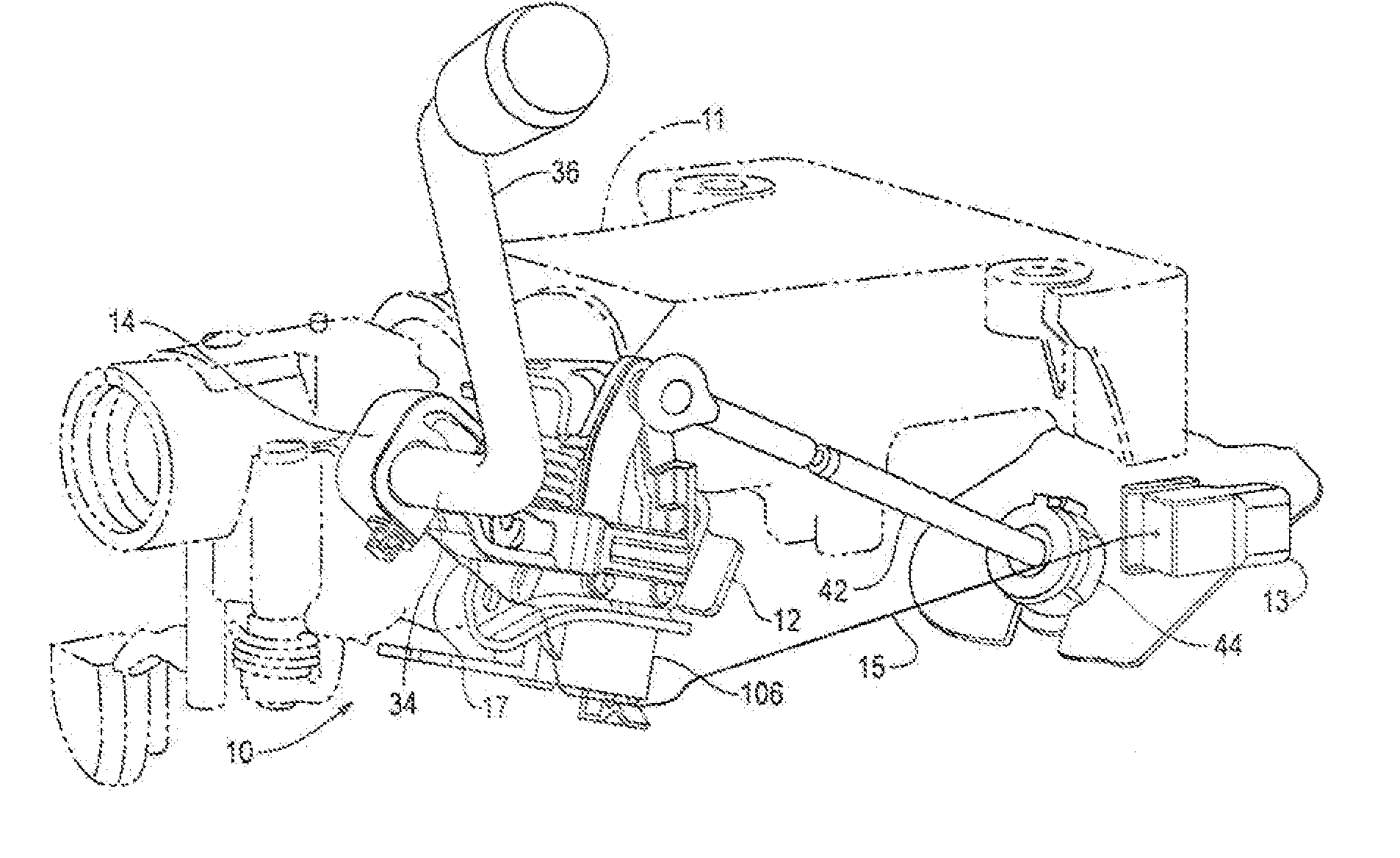
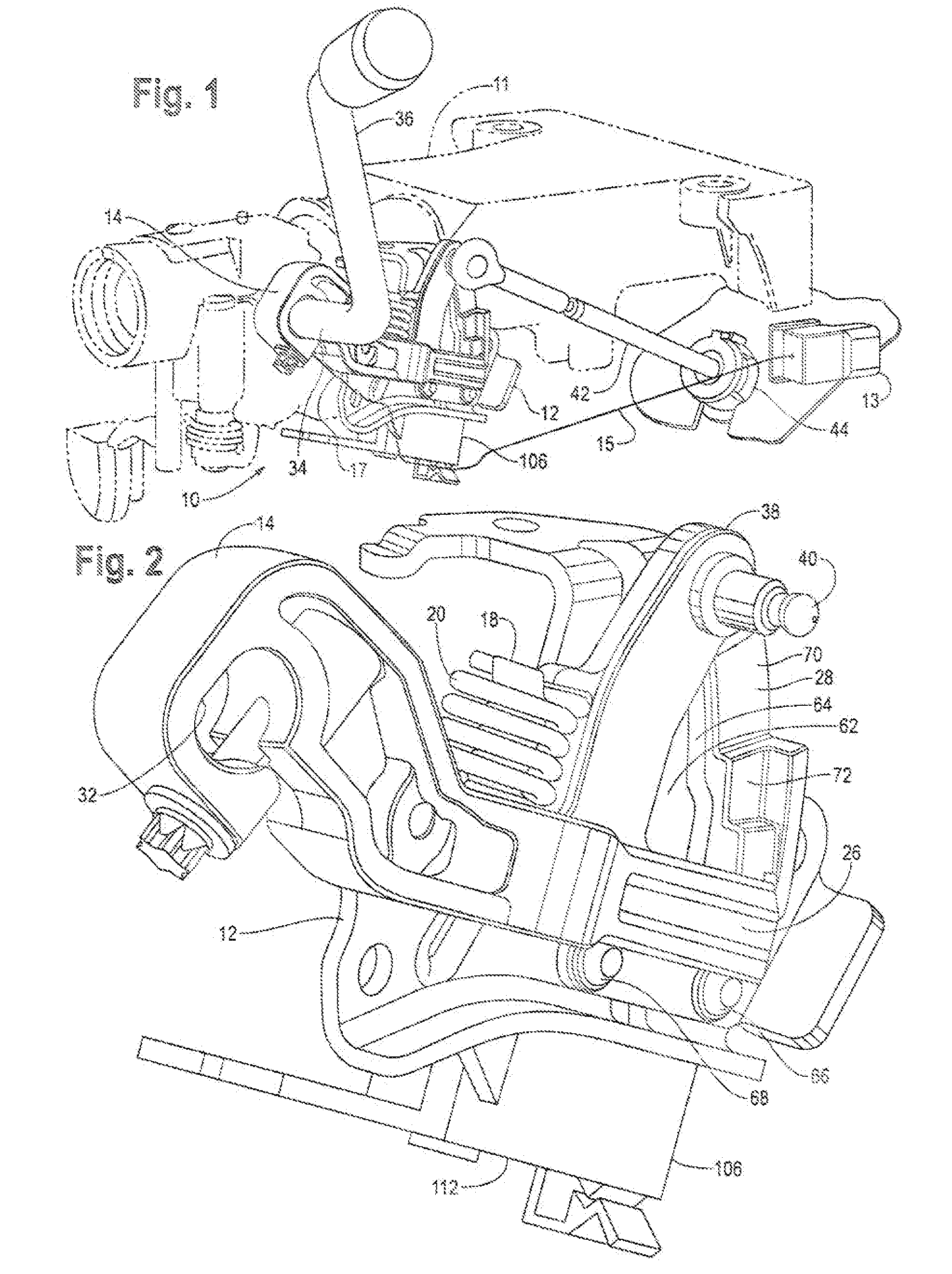
[0020]Referring to FIGS. 1 and 2, the shift module assembly 10 is mounted to a vehicle on the steering column 11 by way of the mounting bracket 12. A swing arm 14 is pivotally supported on the mounting bracket 12 by way of pivot bolt 16 (FIG. 10). The pivot bolt 16 allows the swing arm 14 to pivot in two directions: a limited rocking movement in a plane normal to the plane of mounting bracket 12, and rotational movement around pin 16, as will be explained in further detail. A spring mounting pin 18 (FIG. 2) extends outwardly from swing arm 14, and a cross-over spring 20 is mounted over pin 18. One end 22 of cross-over spring 20 engages the swing arm 14, and the other end 24 (FIG. 6) engages the end of pivot bolt 16 where the pivot bolt extends outward from mounting bracket 12. The cross-over spring 20 applies a constant force to the swing arm 14 relative to mounting bracket 12, maintaining the default position of one end 26 of swing arm 14 pressing against multi-profile gate plate 2...


PUM


Abstract

A shift module assembly for controlling the movement of a vehicle transmission out of a park condition responsive to a condition of the ignition system of the vehicle and responsive to a position of the vehicle brake pedal includes a moveable swing arm adapted to selectively control the condition of the vehicle transmission. The swing arm is in a park position when the vehicle transmission is in the park condition. The swing arm is locked in an immobile position by a solenoid operated armature shaft when the swing arm is placed in the park position. The armature shaft is in direct contact with said swing arm when said swing arm is in the locked position. The armature shaft releases the swing arm from the locked position upon actuation of the vehicle ignition system and depression of the vehicle brake pedal. The swing arm includes a stress line that will cause the swing arm to break along the stress line before, the swing arm is moved out of the park position if excessive force is applied to the swing arm. In addition, the swing arm is capable of both rotational and rocking movement about a common pivot point.

Description

[0001]This invention relates to a shift module assembly having an interlock prohibiting movement of a vehicle's shifting arm and transmission out of a park position until the vehicle brake is depressed and the ignition system is turned on, and prevents removal of the ignition key unless the gear shift selector arm is in the park position. The interlock is located on the shift module directly adjacent the swing arm controlling the condition of the transmission.BACKGROUND OF THE INVENTION[0002]Safety mechanisms which prohibit vehicles from moving when the operator is not in control of the vehicle are very important. Often times, these safety mechanisms are overly complicated aid require many electronic and mechanical moving parts. It is also difficult to incorporate these safety mechanisms into existing modular and compact vehicle components. This creates a problem because of the tendency for overly complicated and widely dispersed mechanical parts that require maintenance or fail com...

Claims


Application Information

Patent Timeline
IPC IPC(8): G05G5/06
CPCF16H59/54F16H61/22F16H63/48Y10T74/20104Y10T74/20648Y10T477/649Y10T477/647F16H2059/746
Inventor AVERS, WAYNEWALDIE, STEVENSCOUT, GREGMCCLUSKEY, DANIELADELMANN, JEFFCARANO, JOE
Owner ADMIRAL TOOL & MFG OF MICHIGAN
Why Eureka
Try Eureka