
Wheel supporting bearing assembly and method for producing the same

a technology for supporting bearings and bearing assemblies, which is applied in the direction of bearing unit rigid support, instruments, transportation and packaging, etc. it can solve the problems of limited machining accuracy enhancement, grinding dust, and metal dust in the finished double-row bearing unit, so as to reduce the internal clearance of the double-row bearing unit in use, the effect of stabilizing the bearing performance and reducing the internal clearan

Inactive Publication Date: 2006-09-14
NSK LTD
View PDF9 Cites 73 Cited by
  • Summary
  • Abstract
  • Description
  • Claims
  • Application Information

AI Technical Summary

Benefits of technology

The present invention relates to a wheel supporting bearing assembly for vehicles, which is used to support rotatably wheels on suspension systems. The assembly includes an outer race, inner races, tapered rollers, and a hub. The hub has a mounting flange for fixing a wheel to a vehicle. The assembly is designed to allow for a proper alignment and secure attachment of the wheel to the vehicle. The technical effects of the invention include improved load bearing capacity, reduced weight, and improved stability of the wheel supporting bearing assembly.

Problems solved by technology

When considering costs, however, there exists a certain limitation on the enhancement of machining accuracy.
When the grinding work is performed in such a state, however, there may be caused a possibility that grinding dust (metallic dust) produced at the time of grinding the inner race intrudes into the inner race unit.
Once grinding dust enters the inner race unit, it is hard to remove it, resulting in a possibility that the grinding dust remains in a completed double-row bearing unit.
Then, the remaining winding dust damages the surfaces of the raceways and the rolling elements 3, 3 when in operation to thereby reduce the life of the double-row bearing unit, which is undesirable.
However, this attempt results in a disadvantage where the cost for the machining apparatus is increased.
Thus, in the event that the axial dimensions of both the inner races 2c, 2b cannot be made substantially equal to each other, since these inner races 2c, 2b are normally produced using different (two) machining lines, an investment cost for facility is increased.

Method used


Image

  • Wheel supporting bearing assembly and method for producing the same
  • Wheel supporting bearing assembly and method for producing the same
  • Wheel supporting bearing assembly and method for producing the same

Examples


embodiment 1

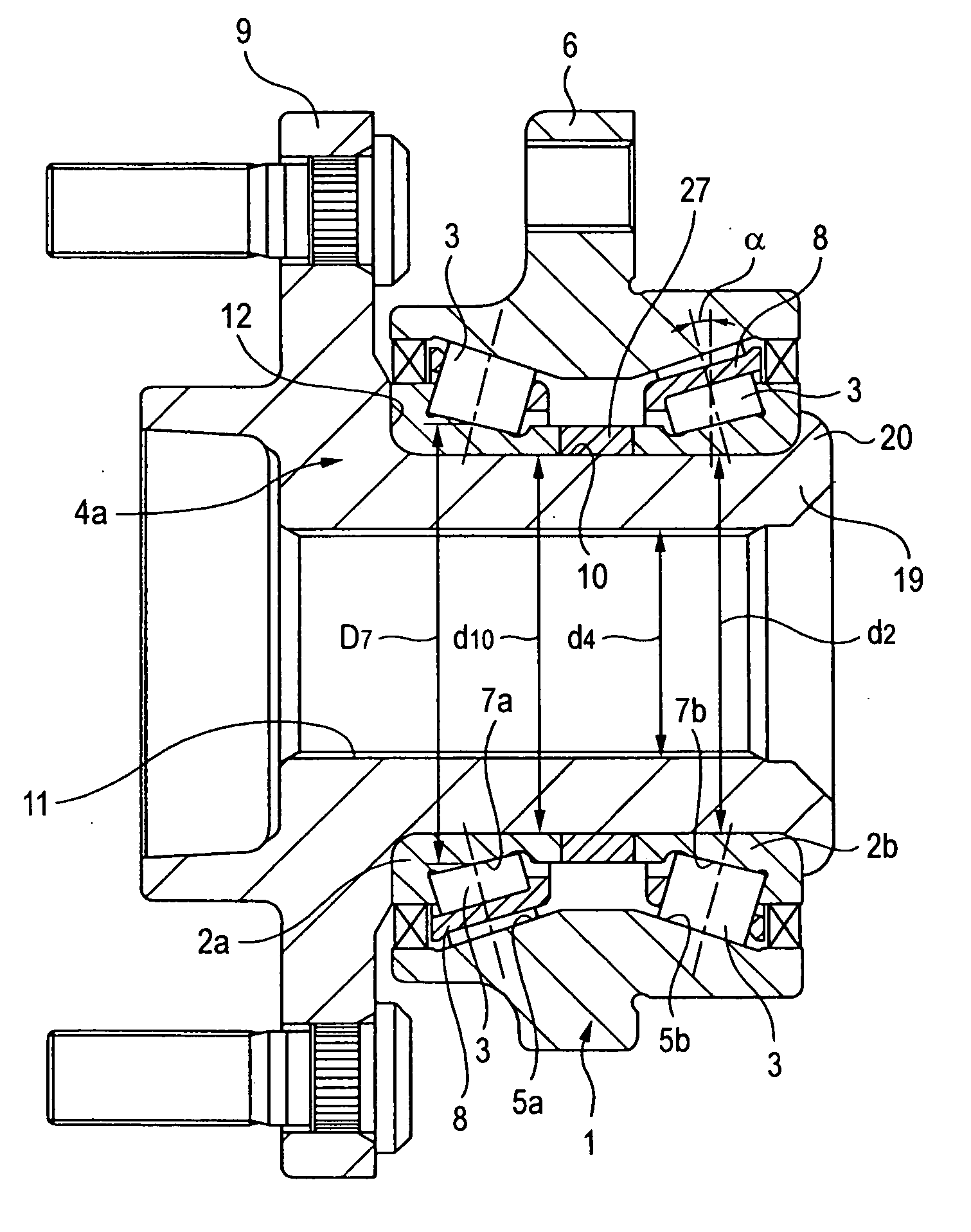
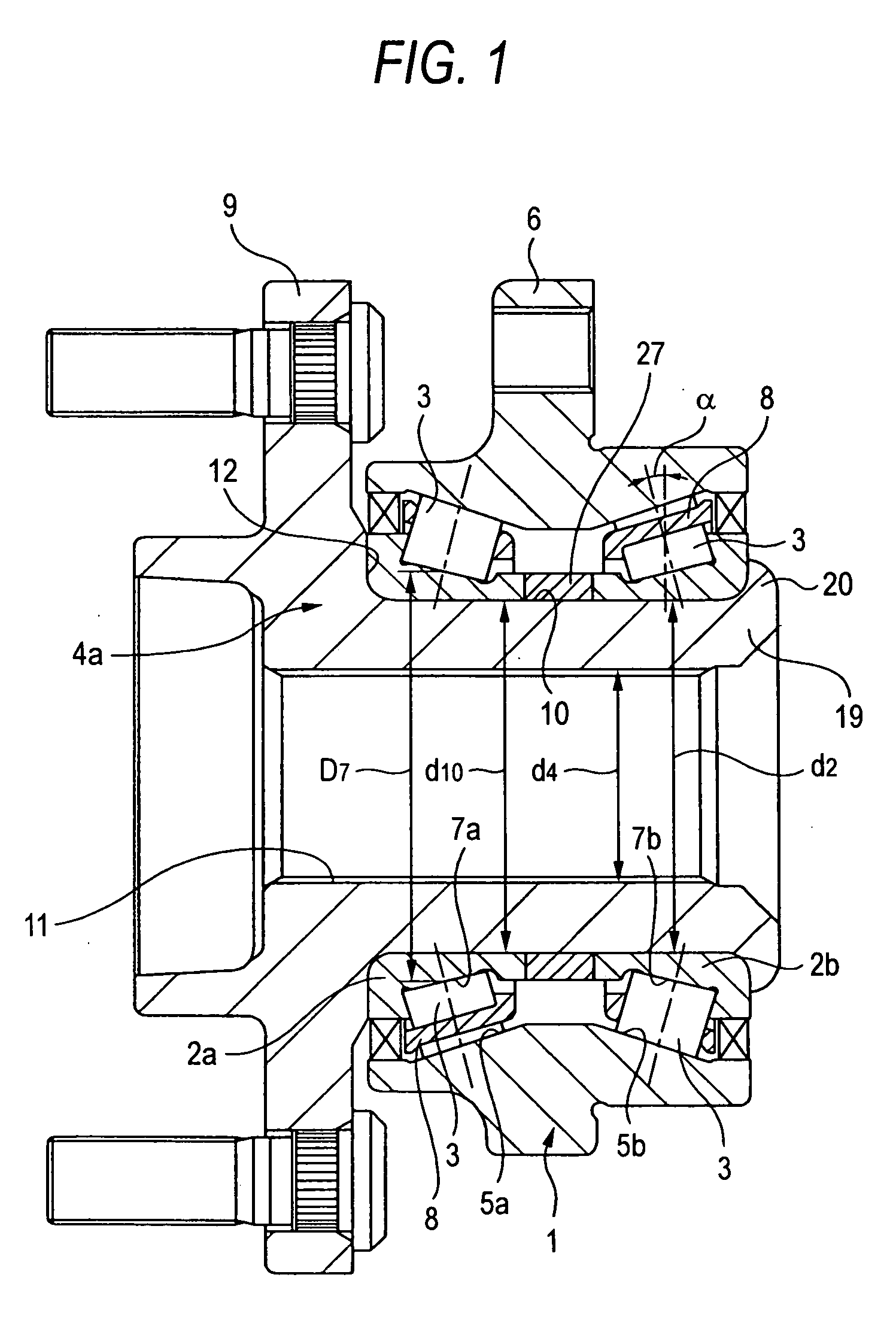
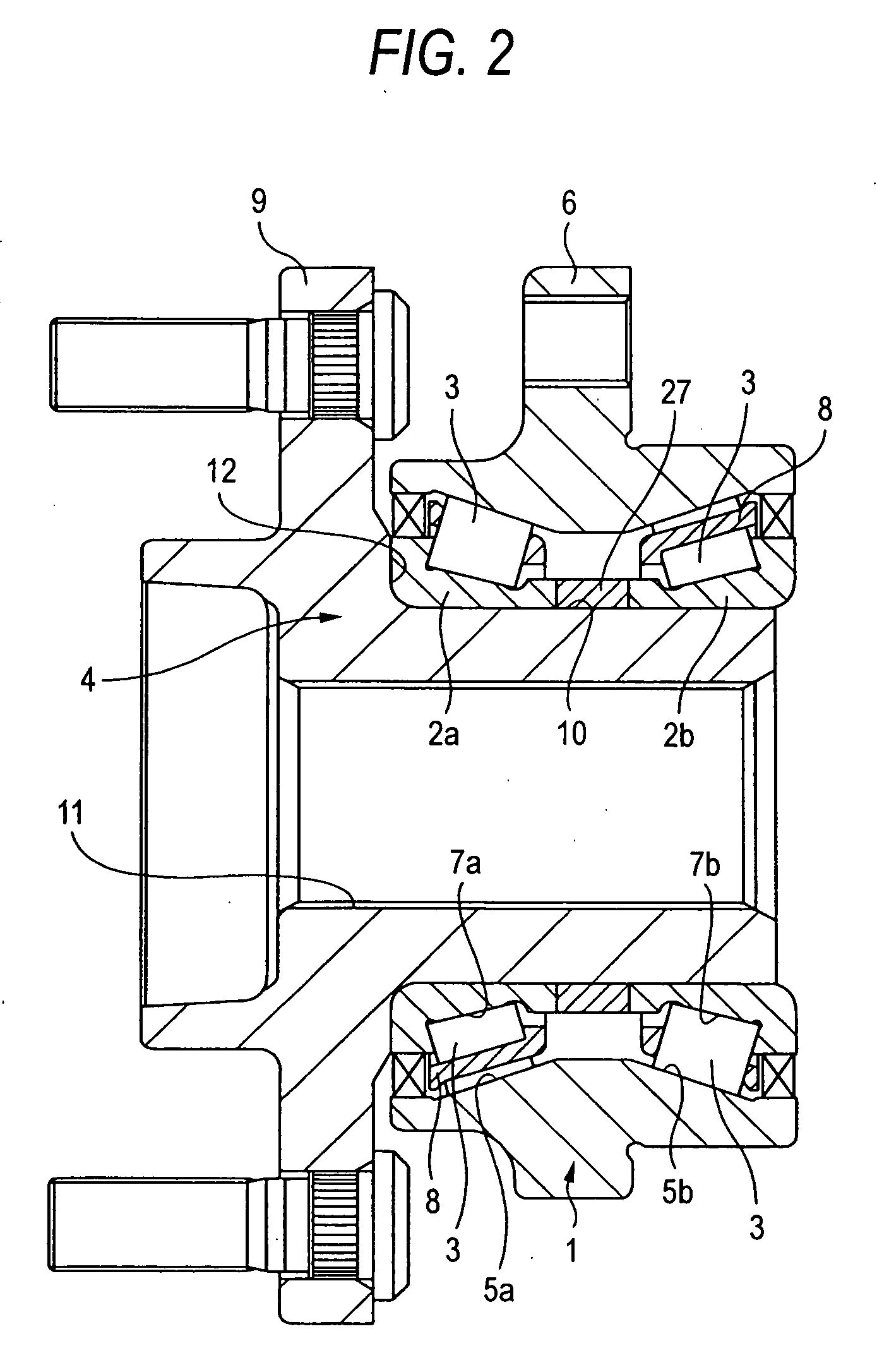
[0077]FIG. 1 shows Embodiment 1 which corresponds to the first, second, sixth, seventh, eighth, ninth, tenth and twelfth aspects of the invention. Note that the characteristics of this embodiment reside in a point that a spacer 27, which has a rectangular section and which is configured into an annular shape as a whole, is held between a small-diameter side end face of a first inner race 2a and a small-diameter side end face of a second inner race 2b which are made to face each other and in a production method for a wheel supporting bearing assembly which includes the spacer 27. The construction and function of the other portions of Embodiment 1 are substantially similar to those of the second example of the conventional construction shown in FIG. 21, and therefore, like reference numerals are given to like portions so that the repetition of a similar description should be omitted or a similar description should be simplified, and the description will be centered at what is characte...

embodiment 2

[0090] Next, Embodiment 2 of the invention which corresponds to the first, second, sixth, seventh, eighth, ninth, tenth and thirteenth aspects of the invention will be described by reference to FIG. 1 which shows Embodiment 1 which has been described above. According to this embodiment, when assembling together constituent parts which make up a wheel supporting bearing assembly after a proper value for an axial internal clearance in a double-row bearing unit in a state resulting before first and second inner races 2a, 2b are fitted on a cylindrical surface portion 10 of a hub 4a with interferences is determined, the double-row assembling unit is assembled by using a spacer 27 which makes up the wheel supporting bearing assembly (by causing the spacer 27 to be held between the first and second inner races 2a, 2b) in place of the standard spacer from the beginning. In addition, the axial internal clearance in the double-row bearing unit in the state resulting before the first and seco...

embodiment 3

[0093] Next, Embodiment 3 of the invention which corresponds to the first, second, sixth, seventh, eighth, ninth, tenth and fourteenth aspects of the invention will be described by reference to FIG. 1 which shows Embodiment 1 which has been described above. According to this embodiment, a plurality of kinds of spacers 27 are prepared in advance which are made slightly different in axial dimension from each other at equal intervals (or at desired intervals which are set arbitrarily) before starting assembly work of individual parts which make up a wheel supporting bearing assembly. Then, as with the Embodiment 1 that has been described before, after a double-row bearing unit has been assembled using the standard spacer 27, an axial internal clearance in the double-row bearing unit in a state resulting before first and second inner races 2a, 2b, which make up the double-row bearing unit, are fitted on a cylindrical surface portion 10 with interferences is measured by a known method. I...


PUM


Abstract

A construction is adopted in which an annular spacer 27 is held between first and second inner races 2a, 2b. An internal clearance in a double-row bearing unit is measured in a middle step of assembling work of a wheel supporting bearing assembly, and in the event that a resultant measured value does not become a proper value, an axial dimension of the spacer 27 is adjusted, so that the internal clearance becomes the proper value. Thereafter, the assembling work is made to continue until the assembling work is completed. A problem which is to be solved by the invention is solved in the way described above.

Description

BACKGROUND OF THE INVENTION [0001] 1. Technical Field [0002] The present invention relates to a wheel supporting bearing assembly which is used to support a wheel on a suspension system in a rolling fashion and a method for producing the same. [0003] 2. Related Arts [0004] Conventionally, wheel supporting bearing assemblies have been used to support rotatably wheels on suspension systems of motor vehicles. FIG. 20 shows a wheel supporting bearing assembly for a driving wheel (one of front wheels of an FF (front engine, front wheel drive) vehicle, one of rear wheels of FR (front engine, rear wheel drive) and RR (rear engine, rear wheel drive) vehicles, one of four wheels of a four-wheel drive vehicle) as a first example of the construction of the conventional wheel supporting bearing assemblies. This wheel supporting bearing assembly includes an outer race 1, first and second inner races 2a, 2b, a plurality of tapered rollers 3, 3 which are each rolling elements and a hub 4, which is...

Claims


Application Information

Patent Timeline
Patent Type & Authority Applications(United States)
IPC IPC(8): F16C41/04F16C13/00F16C32/00
CPCB60B27/00F16C19/185F16C19/386F16C43/04G01P3/443G01P3/446G01P3/488F16C41/007F16C33/60F16C35/063F16C2326/02F16C2229/00
Inventor TAKEHARA, TETSUSENSUI, NATSUKISAKODA, HIRONARIHAGIWARA, NOBUYUKICHIFU, TAKETOSHINAGOSHI, SHINGOTSUZUKI, TOSHIHIDE
Owner NSK LTD
Learn More