Rope

a technology of ropes and ropes, applied in the field of ropes, can solve the problems of rope failure, catastrophic failure of ropes, fiber material loosening a substantial amount of strength,

Inactive Publication Date: 2006-09-21
CORTLAND CABLE
View PDF9 Cites 33 Cited by
  • Summary
  • Abstract
  • Description
  • Claims
  • Application Information

AI Technical Summary

Problems solved by technology

Rope failure may be caused by different damage mechanism, e.g. frictional heat generated within the rope, or self-abrasion.
The frictional heat generated within a rope can be great enough to cause a catastrophic failure of the rope.
This problem is particularly evident when the fiber material looses a substantial amount of strength, i.e. becoming susceptible to creep rupture, when heated above ambient temperature.
These jackets, however, add to the overall diameter, weight, and cost of the rope without any appreciable increase in the rope's strength.
The larger size is obviously undesirable because it would require larger drums, pulleys, or sheaves to handle the jacketed rope.
In addition, rope jackets make visual inspection of the rope core fibers problematic because the jacket hides the core fibers.
Therefore, while this solution may be viable, it is considered unsatisfactory.

Method used


Image

  • Rope
  • Rope
  • Rope

Examples


first embodiment

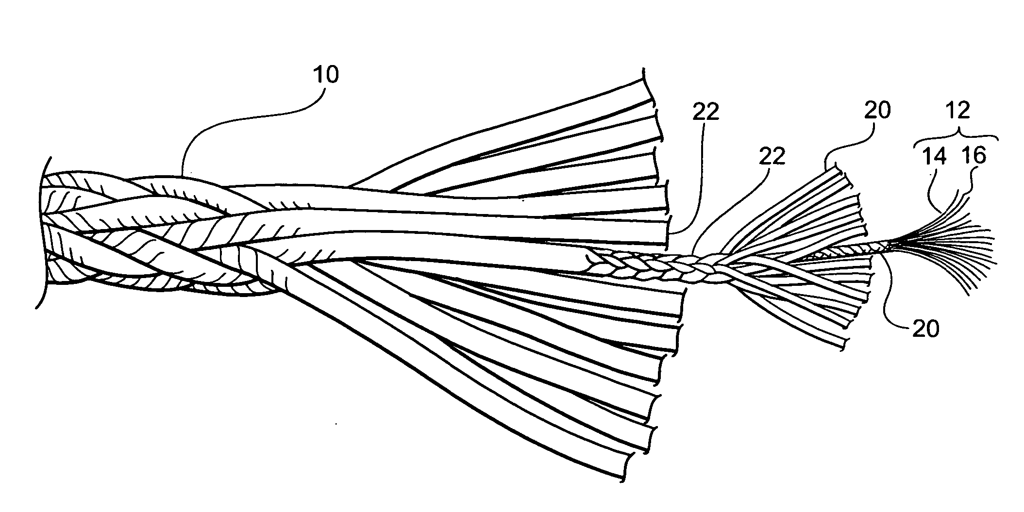
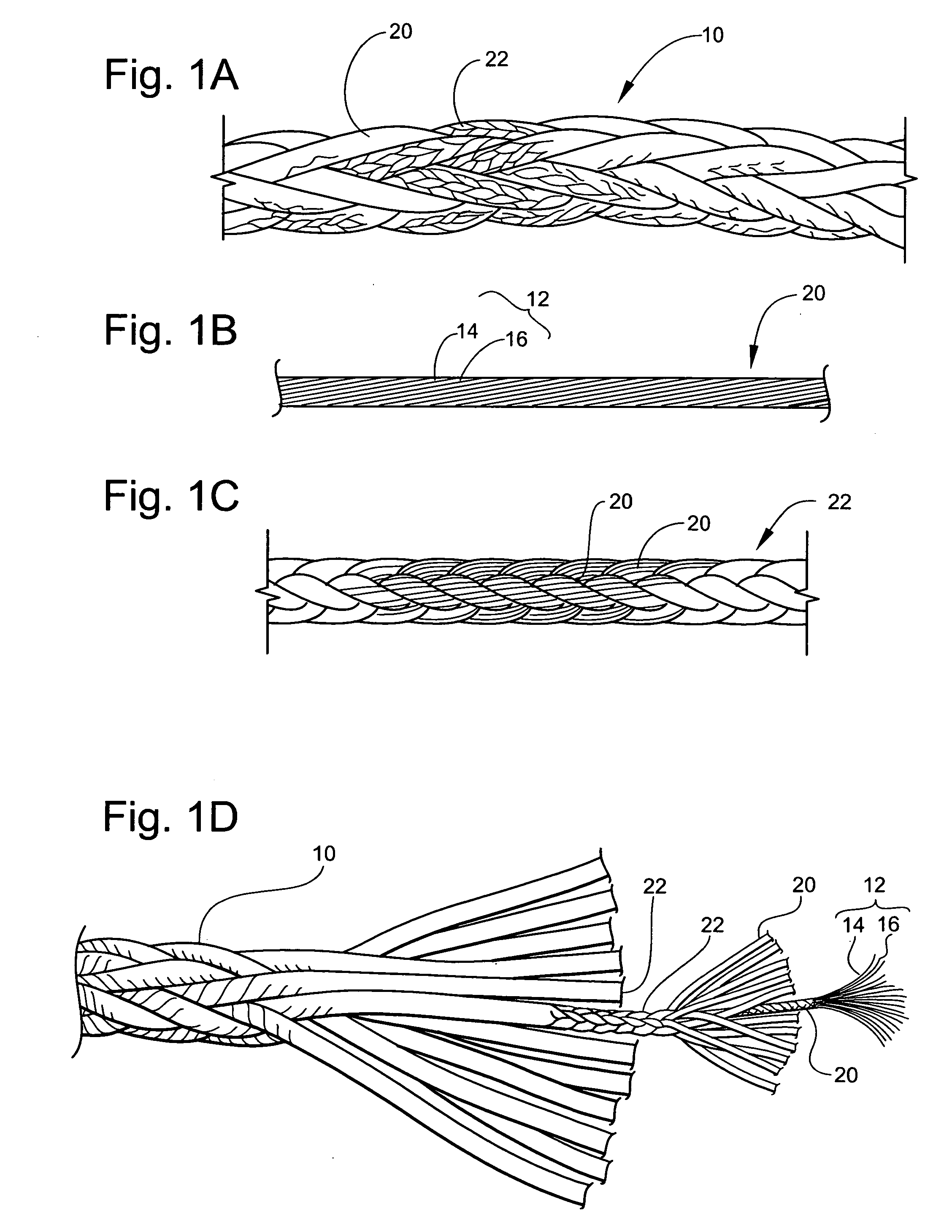
[0029] In construction of rope 10, referring to FIG. 1A-1D, the blend of filaments 12, which includes the first, and second filaments 14, and 16, respectively, is twisted together in a conventional manner to form a twisted yarn 20. The number of the first, and second filaments, 14, and 16 twisted together to form the twisted yarn 20 is not limited. Referring to FIG. 1c, a plurality of twisted yarns 20 is, then in turn, braided together in a conventional manner to from a braided strand 22. The number of twisted yarns 20 braided together to form the strand 22 is not limited. A plurality of braided strands is, subsequently, braided together in a conventional manner to form the rope 10. The number of braided strands 22 to form the rope 10 is not limited.

[0030] In an alternative construction of the first embodiment of rope 10, the blend of filaments 12, which includes first filament 14, second filament 16, and third filament (not shown) is twisted together in a conventional manner to for...

second embodiment

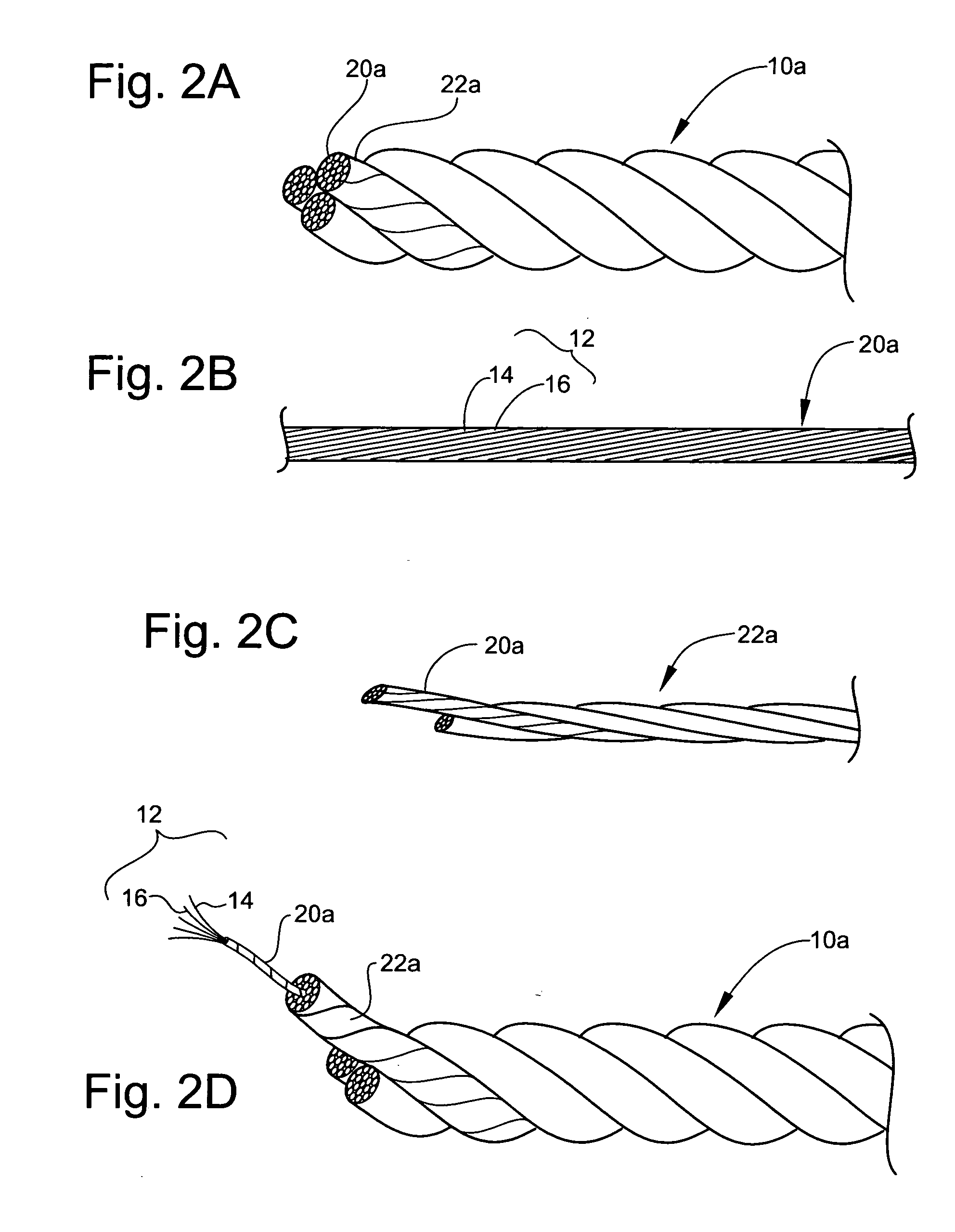
[0031] In construction of rope 10, referring to FIG. 2A-2D, the blend of filaments 12, which includes the first, and second filaments 14, and 16, respectively, is twisted together in a conventional manner to form a twisted yarn 20a. The number of the first, and second filaments, 14, and 16 twisted together to form the twisted yarn 20 is not limited. A plurality of the twisted yarns 20a is, then in turn, twisted together in a conventional manner to from a twisted strand 22a. The number of twisted yarns 20 twisted together to form the strand 22a is not limited. A plurality of twisted strands 22a is, subsequently, twisted together in a conventional manner to form the rope 10a. The number of twisted strands 22a to form the rope 10a is not limited.

[0032] In an alternative construction of the second embodiment of rope 10, the blend of filaments 12, which includes the first filament 14, second filament 16, and third filament (not shown) is twisted together in a conventional manner to form ...

third embodiment

[0033] In construction of rope 10, referring to FIG. 3A-3B, the blend of filaments 12, which includes the first, and second filaments 14, and 16, respectively, is aligned in a substantially parallel relation to each other, and then compacted under tension to form a core 24. The number of the first, and second filaments, 14, and 16 aligned and compacted together to form the core 24 is not limited. The Core 24 is, subsequently, covered by a covering 26. The covering 26 may include, but is not limited to, a synthetic polymer based product.

[0034] In an alternative construction of the third embodiment of rope 10, the blend of filaments 12, which includes the first filament 14, second filament 16, and third filament (not shown) is aligned in a substantially parallel relation to each other, and then compacted under tension to form a core 24. The number of the first filament 14, second filament 16, and third filament aligned and compacted together to form the core 24 is not limited. The Cor...


PUM

PropertyMeasurementUnit
molecular weightaaaaaaaaaa
strengthaaaaaaaaaa
tensionaaaaaaaaaa

Abstract

The instant invention is a rope. This rope includes a blend of filaments including a first filament, and a second filament. The second filament is fluorocarbon polymer filament.

Description

FIELD OF INVENTION [0001] The instant application relates to a rope for various types of applications including, but not limited to, heavy lifting or mooring applications, such as marine, oceanographic, offshore oil and gas, seismic, and industrial applications. BACKGROUND OF THE INVENTION [0002] The use of ropes in various applications is widely known. Generally, a rope may be a stout cord made of strands of natural or artificial fibers twisted or braided together, or in the alternative, a rope may be a cord having a wire core with fiber strands braided around it. [0003] Different factors must be considered in order to prevent rope failure. These factors include, but are not limited to, rope construction methods, fiber selections, and service conditions. Rope failure may be caused by different damage mechanism, e.g. frictional heat generated within the rope, or self-abrasion. The frictional heat generated within a rope may be caused by the bending mechanism; or in the alternative, ...

Claims


Application Information

Patent Timeline
Patent Type & Authority Applications(United States)
IPC IPC(8): D04C1/00
CPCD04C1/12D07B1/02D07B1/025D07B1/04D07B2201/1092D07B2201/1096D07B2201/2036D07B2201/2041D07B2201/209D07B2205/2014D07B2205/2042D07B2205/205D07B2205/2096D07B2801/10D07B2205/2071D07B2401/207D07B2201/1014D07B2201/20903
Inventor NYE, RICHARD E.
Owner CORTLAND CABLE
Why Eureka
Try Eureka