Mud flap bracket

a technology of mud flaps and brackets, which is applied in the direction of superstructure subunits, vehicle components, transportation and packaging, etc., can solve the problems of driver ticketing, liable for road debris damage to other vehicles, and difficulty in reinstalling mud flaps along the roadside or other remote locations

Inactive Publication Date: 2006-09-21
COLLINS RODNEY +1
View PDF11 Cites 8 Cited by
  • Summary
  • Abstract
  • Description
  • Claims
  • Application Information

AI Technical Summary

Benefits of technology

[0005] The invention overcomes the above-noted and other deficiencies of the prior art by providing a mud flap bracket, installed by use of a simple hand tool, that is configured to grip lateral I-beam support

Problems solved by technology

Reinstalling a mud flap along the roadside or other remote location is often difficult due to the range in types of mud flap attachments and specialized equipment required for their installation (e.g., welding equipment).
How

Method used


Image

  • Mud flap bracket
  • Mud flap bracket
  • Mud flap bracket

Examples


Embodiment Construction

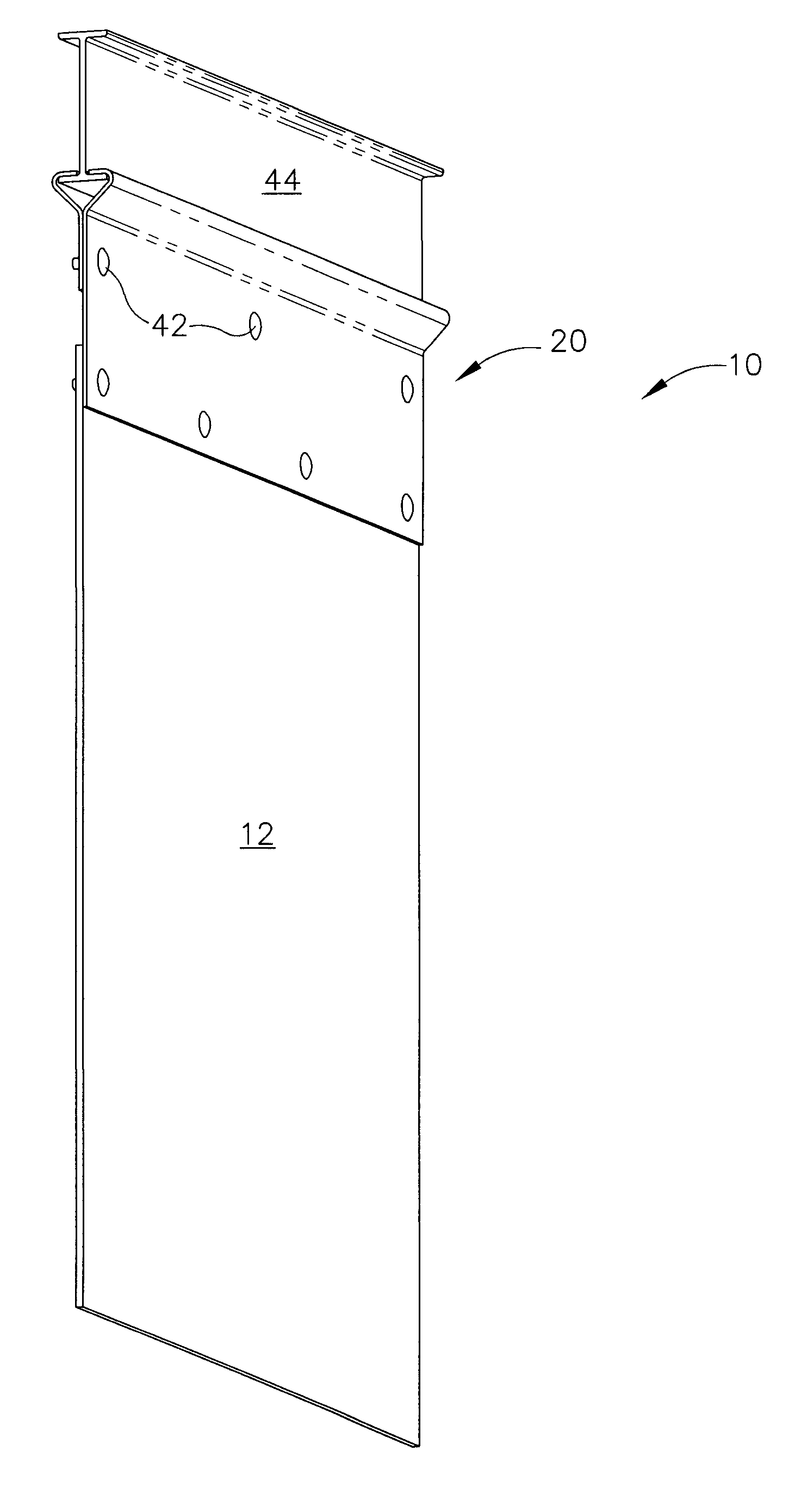
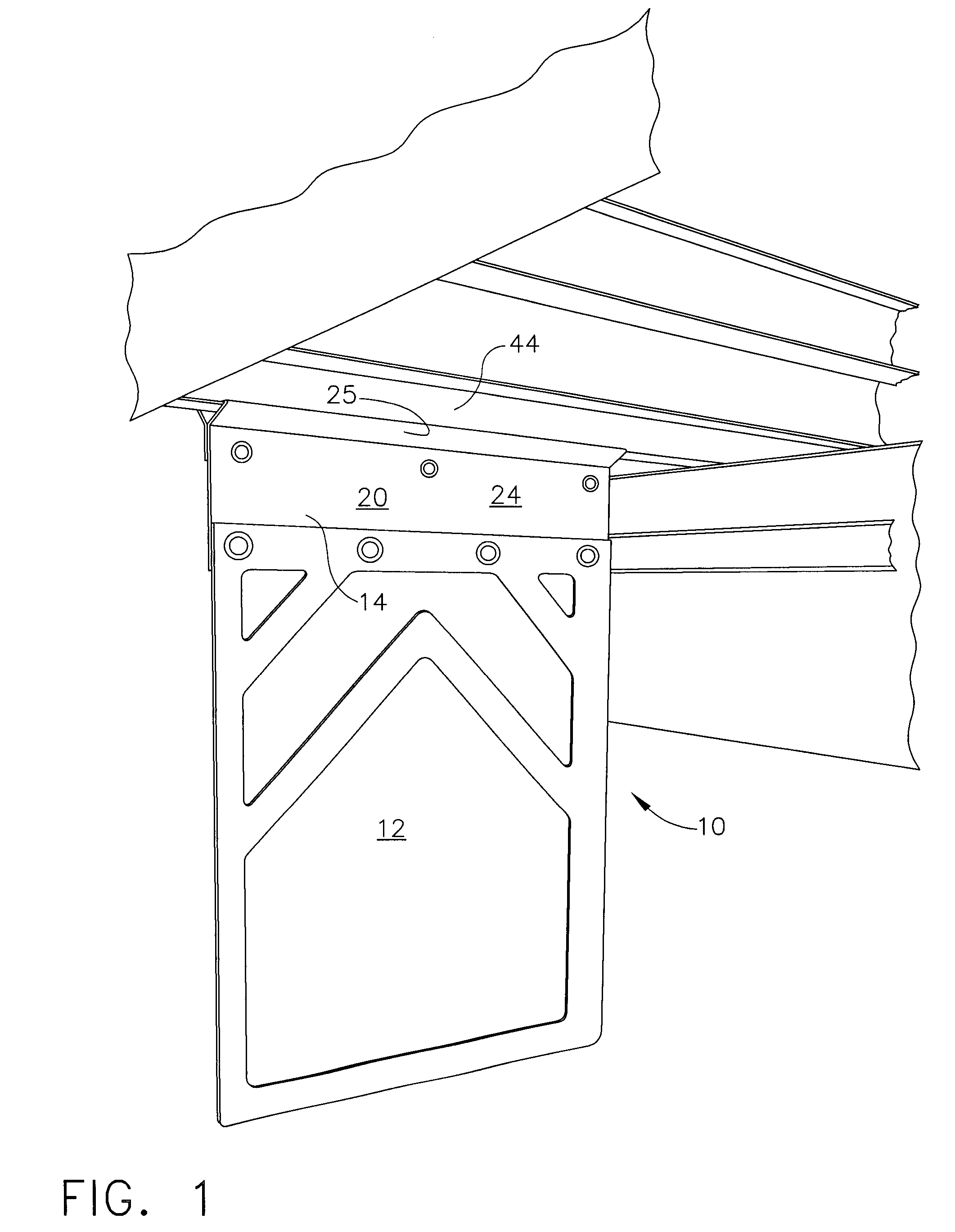
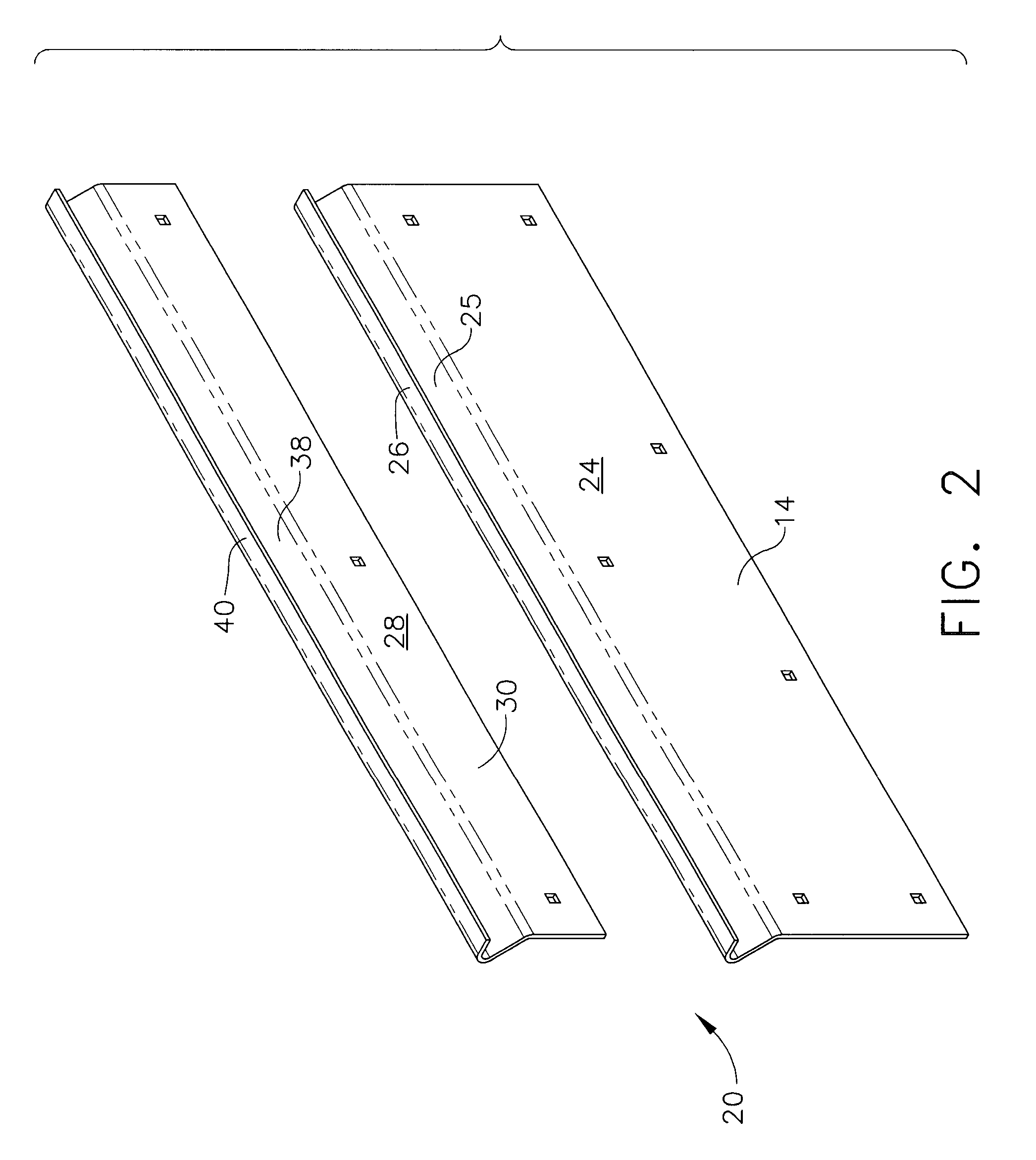
[0014] In FIGS. 1-5, a mud flap assembly 10 includes a mud flap 12, its upper portion overlapped and bolted to a vertical lower portion 14 of a two-piece mud flap bracket 20. In particular, the lower portion 14 is part of a first bracket member 24 that is bent along its horizontal width near its top into an acute angle from the vertical (e.g., 45° degrees) to form an outwardly extending portion 25 and then is bent again along its horizontal width closer yet to its top back in the other direction to form a near horizontal gripping flange 26. It should be appreciated that these angles may be formed by bending sheet metal, extruding a material in this shape, or by other fabrication techniques that include assembling a plurality of components.

[0015] A second bracket member 28 includes a shorter vertical portion 30 that parallels the vertical lower portion 14 of the first bracket member 24 between the top edge of the mud flap 12 and the first bend (outwardly extending portion 25) in the...


PUM


Abstract

A mud flap assembly lends itself to a field installed kit by including two opposing flanges with inwardly opposing hooked edges that are drawn together by bolted vertical plates to grip a lower plate of a lateral I-beam prevalently used on semi-tractor trailers. Thereby, simple tools may be used even in austere locations in order to replace an OEM mud flap and mud flap attachment that are damaged, such as when a tire blows off its tread. Thereby, problems are avoided such as receiving a ticket for violating traffic regulations, becoming liable for damage due to road debris impacting other vehicles, and incurring lost time costs if grounded at a state border weigh station pending repair.

Description

CROSS REFERENCE TO RELATED APPLICATION [0001] The present application claims the benefit of U.S. Pat Appln. Ser. No. 60 / 662,429 of the same title filed Mar. 16, 2005, the disclosure of which is hereby incorporated by reference in its entirety.FIELD OF THE INVENTION [0002] The present invention relates, in general, to devices that attach a mud flap to a truck. BACKGROUND OF THE INVENTION [0003] Semi-tractor trailers utilize a large number of tires at relatively high pneumatic pressure. Often these tires are retreaded for economic reasons. Over the numerous miles driven on these tires, occasionally a tire will shed its tread taking out the adjacent mud flap and its attachment. Reinstalling a mud flap along the roadside or other remote location is often difficult due to the range in types of mud flap attachments and specialized equipment required for their installation (e.g., welding equipment). However, driving without a mud flap subjects the driver to being ticketed, to being liable ...

Claims


Application Information

Patent Timeline
IPC IPC(8): B62D25/18
CPCB62D25/188
Inventor COLLINS, RODNEYCOLLINS, ELIJAH
Owner COLLINS RODNEY
Why Eureka
Try Eureka