Organic electro-luminescence device, driving method thereof and electronic apparatus

an electroluminescence device and driving method technology, applied in the direction of instruments, static indicating devices, etc., can solve the problems of low brightness of displaying, problem of increasing the size of an organic el device, and lowering the emission life and luminance, so as to achieve the effect of shortening the effective emission time period

Inactive Publication Date: 2006-09-21
SEIKO EPSON CORP
View PDF12 Cites 33 Cited by
  • Summary
  • Abstract
  • Description
  • Claims
  • Application Information

AI Technical Summary

Benefits of technology

[0009] An advantage of some aspects of the invention is to provide an organic EL device that can display images without shortening its effective emission time periods even when AC driving is implemented therefor to alternately apply forward and reverse biases to emission layers

Problems solved by technology

The accumulated impurity ions trap holes or electrons injected from the electrode, which problematically lowers the emission life and luminance.
Therefore, the effective emission time periods are short, which leads to a problem of low brightness of displaying.
Accordingly, the

Method used


Image

  • Organic electro-luminescence device, driving method thereof and electronic apparatus
  • Organic electro-luminescence device, driving method thereof and electronic apparatus
  • Organic electro-luminescence device, driving method thereof and electronic apparatus

Examples


Embodiment Construction

[0062] Organic EL devices according to embodiments of the invention, a driving method thereof, and an electronic apparatus will be described below with reference to the accompanying drawings. It should be noted that the following embodiments only show part of aspects of the invention. It should also be noted that the embodiments do not limit the invention but can optionally be changed within the technical idea of the invention. In the following drawings, different scale is used for each layer and each member in order to illustrate the layers and members with a recognizable size in the drawings.

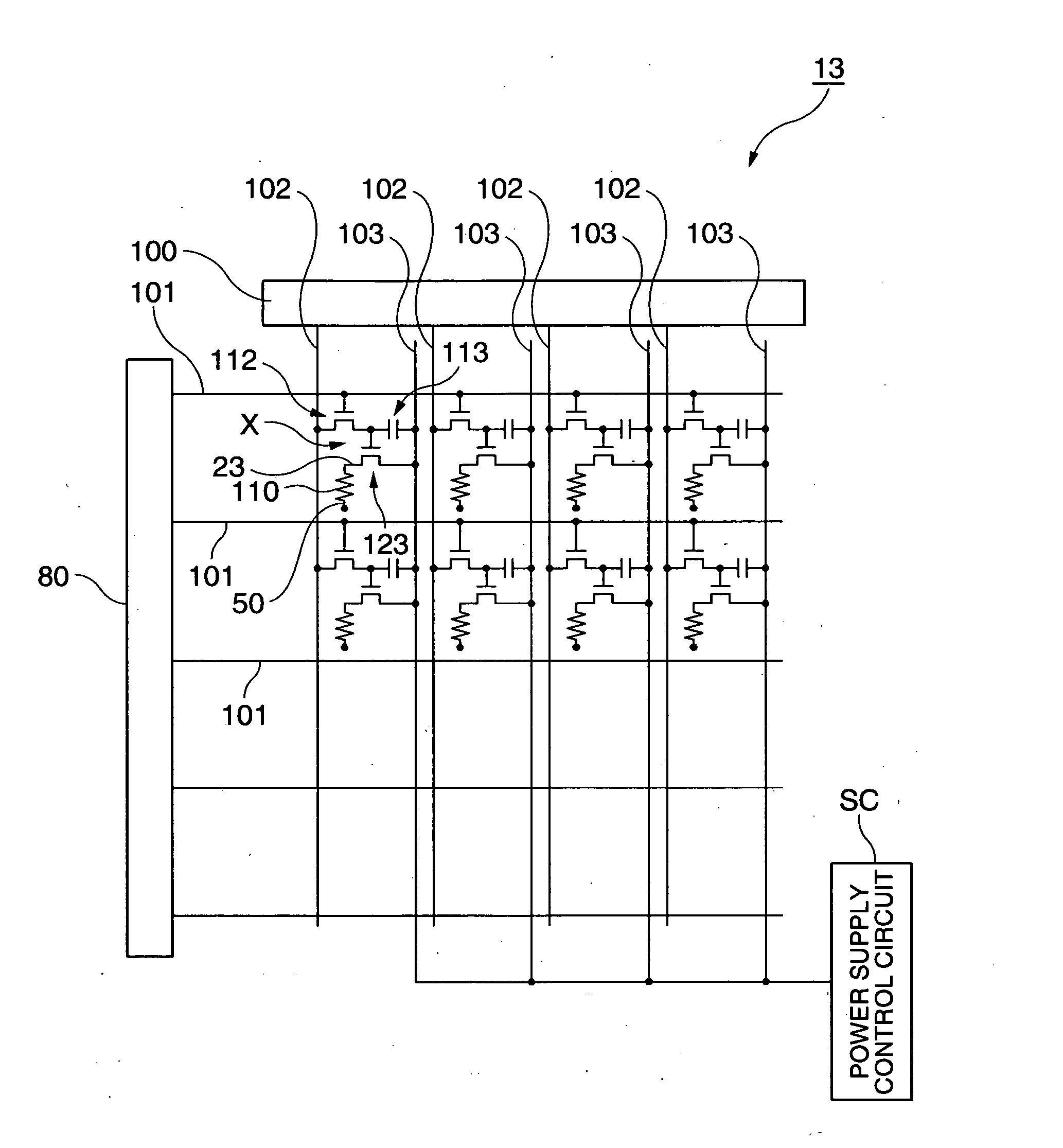
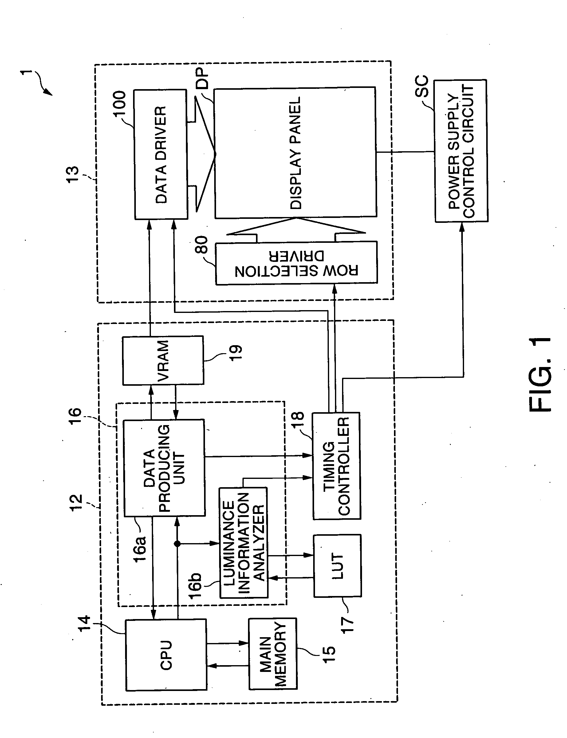
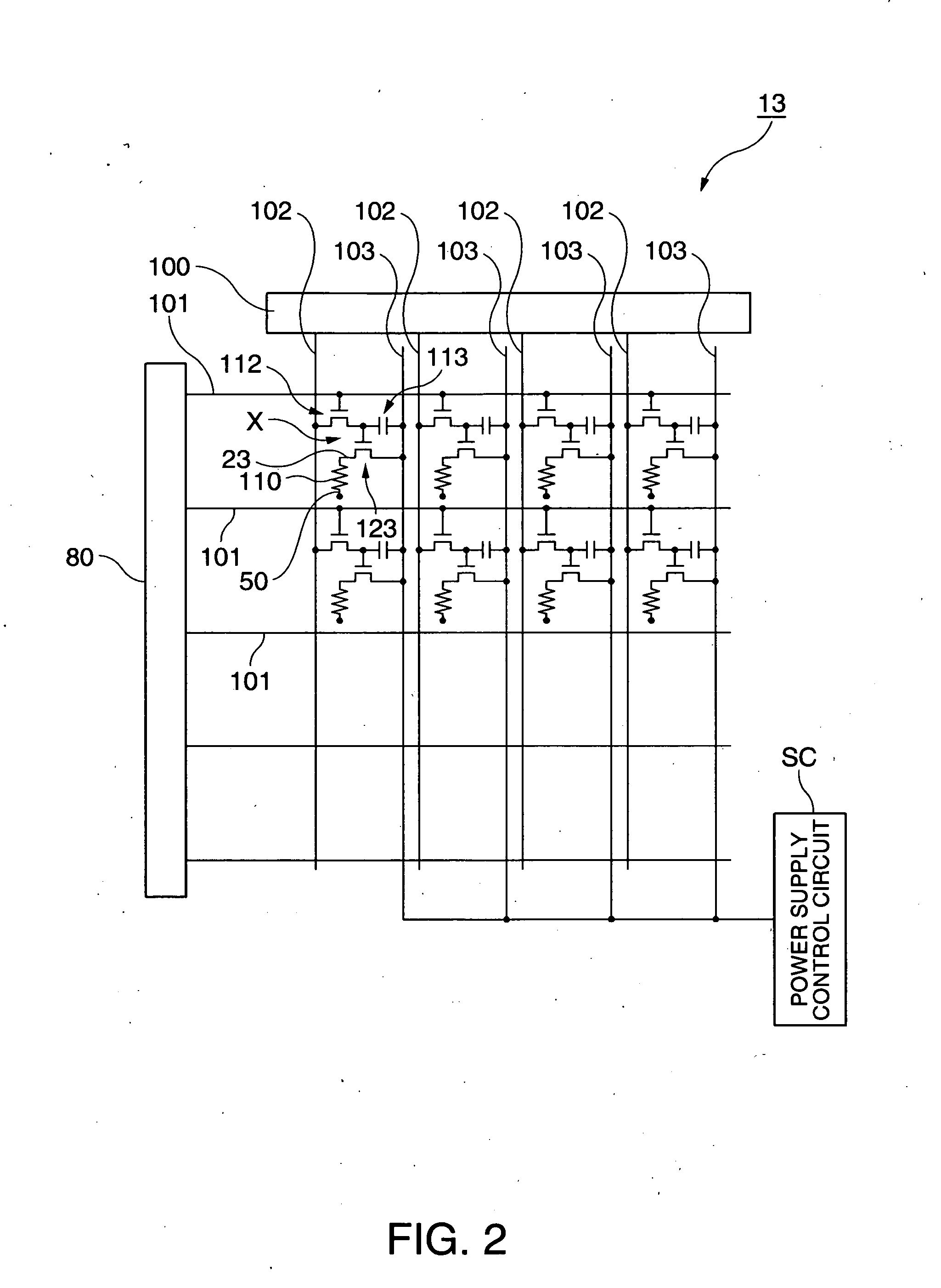
[0063]FIG. 1 is a block diagram illustrating the electrical configuration of an organic EL device according to one embodiment of the invention. Referring to FIG. 1, an organic EL device 1 of the present embodiment includes a peripheral drive device 12 and a display panel unit 13. The peripheral drive device 12 includes a central processing unit (CPU) 14, a main memory 15, a graphic controller...


PUM


Abstract

An organic electro-luminescence (EL) device including at least an emission layer between an anode and a cathode that are opposed to each other, including an anode buffer layer that is composed of an electrically conductive material and is provided between the anode and the emission layer, a cathode buffer layer that is composed of an electrically conductive material and is provided between the cathode and the emission layer, and a drive unit that applies a forward bias voltage and a reverse bias voltage that have opposite polarities to the anode and the cathode with setting application time periods of the forward bias voltage and the reverse bias voltage according to a luminance ratio of an image to be displayed.

Description

BACKGROUND OF THE INVENTION [0001] 1. Technical Field [0002] The present invention relates to an organic electro-luminescence (EL) device, a driving method thereof and an electronic apparatus. [0003] 2. Related Art [0004] In recent years, increasing attention is being paid to organic EL devices employing organic EL elements as a self-luminous element requiring no backlight or the like. The organic EL display includes an organic EL layer, i.e., an emission layer between a pair of opposed electrodes. The organic EL element for full-color displaying includes emission layers that each have an emission wavelength band corresponding to a respective one of colors of red (R), green (G) and blue (B). Voltage application across the opposed electrodes induces recombination of injected electrons and holes in the emission layer, which leads to light emission by the light emitting element. The light emitting elements in the organic EL device are typically formed of thin films having a film thickn...

Claims


Application Information

Patent Timeline
IPC IPC(8): G09G3/00
CPCG09G3/3233G09G2310/0254G09G2320/066G09G2360/16
Inventor HARA, HIROYUKIMAKIURA, RIE
Owner SEIKO EPSON CORP
Why Eureka
Try Eureka