
Spikeless tie plate fasteners, pre-plated railroad ties and related assemblies and methods

a technology of pre-plated railroad ties and tie plate fasteners, which is applied in the direction of track superstructure, ways, constructions, etc., can solve the problems of high cost, high cost, and high risk of trains traveling over the track, so as to prevent or alleviate layer separation and layer shifting

Inactive Publication Date: 2006-09-28
OLLENDICK DAVID
View PDF6 Cites 21 Cited by
  • Summary
  • Abstract
  • Description
  • Claims
  • Application Information

AI Technical Summary

Benefits of technology

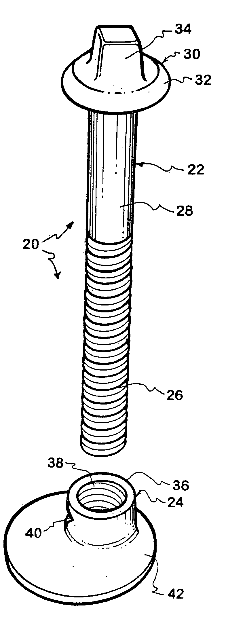
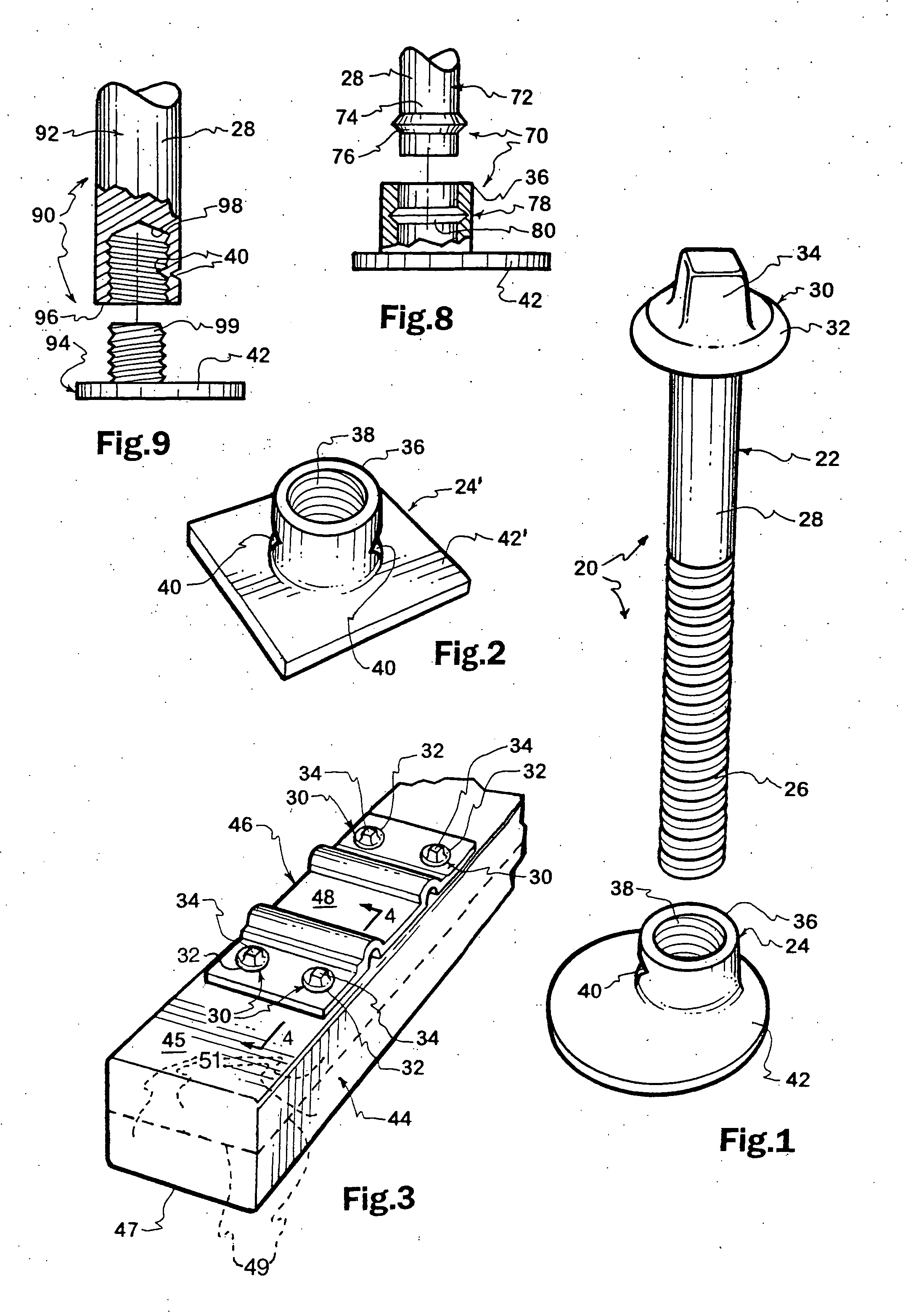
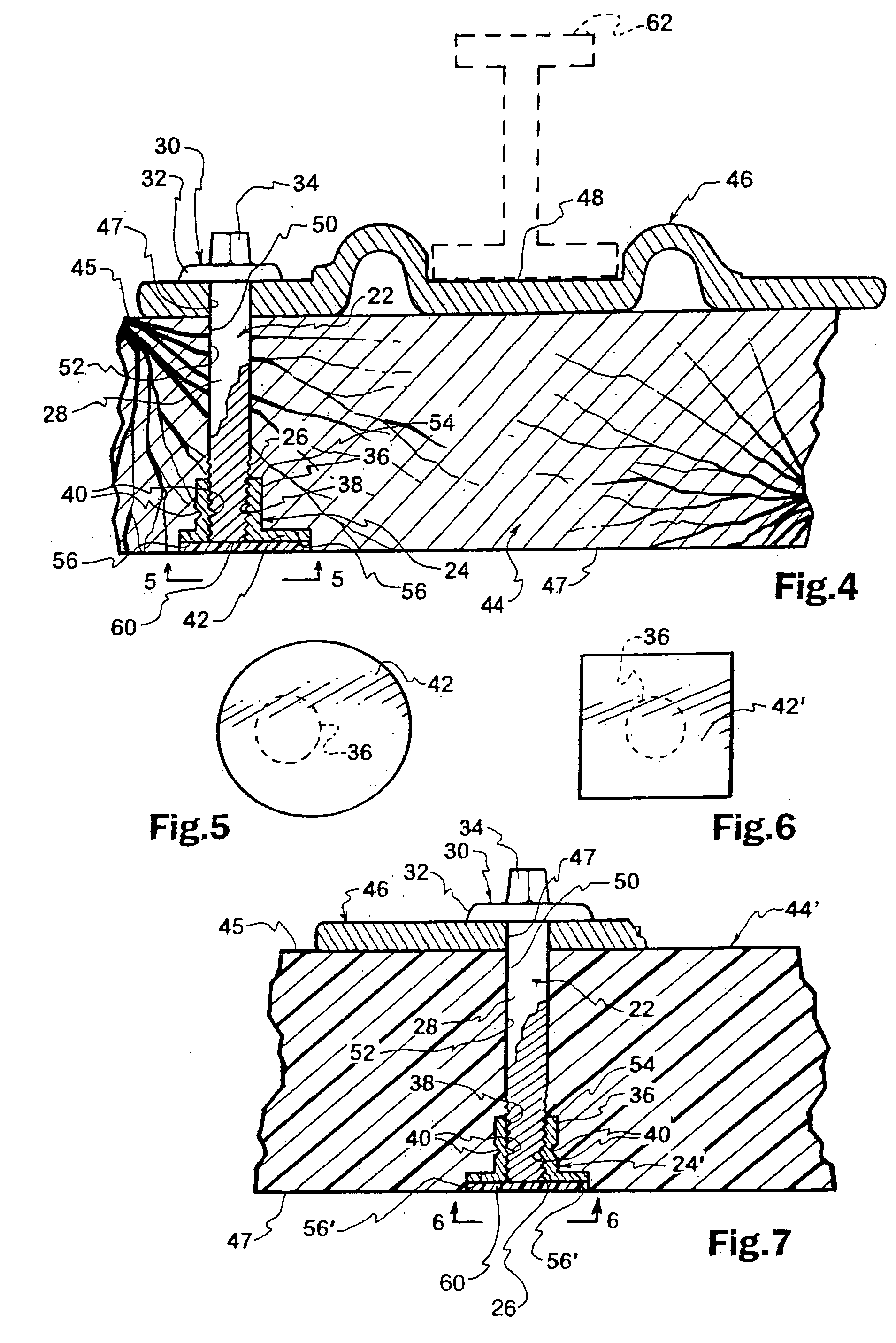
[0010] Typically, each two-part fastener comprises a first or top shaft fastener member inserted through aligned tie plate and tie apertures so that a proximal head thereof is contiguous with the top surface of the associate tie plate. A distal end portion of the first fastener member is disposed within the associated tie aperture and is not connected to the tie. The distal end portion, in the assembled state, is disposed above the bottom surface of the tie in the associated tie aperture. The other, lower or bottom fastener member is inserted from the bottom of the tie into the associate tie aperture, in non-rotatable relation. The other fastener member is preferably entirely disposed within the associate tie aperture (to better allow stacking of pre-plated railroad ties in inventory and on transportation vehicles) and may be covered by a layer or seal for the purpose of protecting the other fastener member from corrosion infiltrating from the ballast. The two-part fastener prevents or alleviates layer separation and shifting when used with multi-layered ties.
[0012] Another paramount object is the provision of a novel system, unique assemblies and distinct methodology for building railroads, pre-plating railroad ties comprising at least one spikeless fastener and at least one driven spike, the spikeless fastener comprising two-parts for use in pre-formed apertures of railroad ties to assist in securing tie plates in position, which features are especially effective with ties formed of hard dense material, such as hard woods, high molecular weight plastics and dense composites.
[0014] Another significant object is to provide novel combinations comprised of a multi-layered railroad tie, tie plates and two-part spikeless fasteners, which prevent or alleviate layer separation and layer shifting.

Problems solved by technology

If the spikes loosen, the associated tie plate will also loosen, creating a potential for damage and a danger for trains traveling over the track.
While the driven-spike-only approach typically works well with soft wood and other soft materials, it often does not with hard woods and other hard materials.
While hard wood ties last longer than soft wood ties, hard wood ties are too often split by the spikes as the spikes are driven.
Thus, the split hard wood tie does not compressively hold the spikes in the fully driven position and the tie plates become loose creating the potential for damage and danger as mentioned above.
Use of nut and bolt fasteners in lieu of and / or together with spikes for hard wood ties has heretofore been rejected in the railroad industry because of the cost of pre-drilling the ties and the nut and bolt fasteners, and difficulty in stacking such pre-plated ties in inventory and on transportation vehicles.
Tightening of such bolts into associated nuts, to retain an associated tie plate tightly on the tie, has been problematic because the nut not only extends below the bottom of the tie, but often rotates as the bolt is rotated.
Screw spikes, which tend to cause the tie to split, have also been proposed for holding tie plates correctly on top of railroad ties, but the screw spikes tend to fracture, under the forces of train vibration over time, at the reduced diameter site located between the shank and the top of the threads.
Use of multiple layer ties has fallen into disfavor, largely because of layer separation and shifting.

Method used


Image

  • Spikeless tie plate fasteners, pre-plated railroad ties and related assemblies and methods
  • Spikeless tie plate fasteners, pre-plated railroad ties and related assemblies and methods
  • Spikeless tie plate fasteners, pre-plated railroad ties and related assemblies and methods

Examples


Embodiment Construction

[0028] Reference is now made to the drawings wherein like numerals are used to designate like parts throughout. As mentioned above, when hard wood ties are used to build or renovate a railroad track, the traditional method of utilizing railroad spikes is often counterproductive because the spikes tend to split the hard wood so that the embedded end of the spikes are not held tightly in position and, therefore, loosen responsive to railroad vibrations as trains move along the track. This can and does create certain risks of damage and danger and increases the amount of maintenance attention required. The same difficulty tends to exist when other dense materials are used, such as high molecular weight synthetic resinous materials and dense composite materials. While the present invention is directed toward railroad ties made of dense material, the present invention works well with softer tie materials, such as soft woods.

[0029] Central to the present invention is to utilize preformed...


PUM


Abstract

Railroad tie plates secured collectively by spikeless fasteners to a tie with railroad spikes securing the rails to the ties and related methodology are disclosed wherein two-part fasteners are used in respect to sets of aligned tie and tie plate apertures such that the two fastener parts are joined together against inadvertent separation within each tie aperture at a connection or union site, which includes but is not limited to force fit unions and threaded unions, and spikes are driven into the ties through other tie plate apertures.

Description

CONTINUITY [0001] This application is a continuation-in-part of my co-pending U.S. patent application Ser. No. 11 / 089,164, filed Mar. 24, 2005.FIELD OF INVENTION [0002] The present invention relates generally to tie-supported railroad tracks and more particularly to spikeless tie plate fasteners, pre-plated railroad ties having at least one spikeless tie plate fastener and at least one spike fastener through each tie plate, related assemblies and methods. BACKGROUND [0003] In regard to railroad ties formed of wooden, plastic and composite materials, some of which may comprise one piece or multiple layers, traditionally only spikes are driven through apertures in two-spaced tie plates, each placed on top of each tie, into non-apertured tie locations. The extent to which the spikes, once driven, and the tie plates through which the spikes pass are held in place depends on the compression forces of the tie material against each spike. If the spikes loosen, the associated tie plate will...

Claims


Application Information

Patent Timeline
IPC IPC(8): E01B21/04
CPCE01B3/46E01B9/02E01B9/54
Inventor OLLENDICK, DAVID
Owner OLLENDICK DAVID
Learn More