Optical system for collimating elliptical light beam and optical device using the same

an optical system and elliptical light technology, applied in the field of optical systems for collimating elliptical light beams, can solve the problems of high-power laser diodes, which are not only more expensive, but also consume more power, and achieve the effect of efficient collimation of elliptical light beams and low power

Inactive Publication Date: 2006-09-28
HON HAI PRECISION IND CO LTD
View PDF4 Cites 0 Cited by
  • Summary
  • Abstract
  • Description
  • Claims
  • Application Information

AI Technical Summary

Benefits of technology

[0009] An exemplary embodiment of the present optical system is for efficiently collimating an elliptical light beam and providing a substantially round light beam for reading / writing to an optical disk.
[0011] An advantage of the optical system is that it can efficiently collimate the elliptical light beam emitting from the light source.
[0012] Another advantage is that a light source of relatively low power can be used in the optical system.

Problems solved by technology

However, high-power laser diodes are not only more costly, but also consume more power.

Method used


Image

  • Optical system for collimating elliptical light beam and optical device using the same
  • Optical system for collimating elliptical light beam and optical device using the same
  • Optical system for collimating elliptical light beam and optical device using the same

Examples


Embodiment Construction

[0020] Reference will now be made to the drawings to describe in detail the preferred embodiments of the present optical system and an optical device using the same.

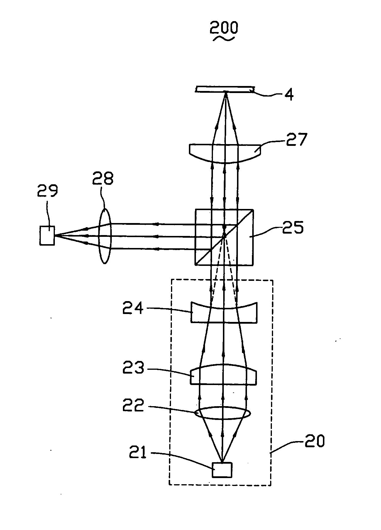
[0021] Referring to FIG. 4, this are respectively a schematic top view and a schematic front view mainly of an optical system 20 for collimating elliptical light beams according to an exemplary embodiment of the present invention. The optical system 20 includes a light source 21, a first lens 22, a second lens 23, and a third lens 24 arranged in that sequence. The light source 21 is adapted for emitting a diverging elliptical light beam along a path coinciding with optical centers of the first lens 22, the second lens 23 and the third lens 24. Any cross-section of the elliptical light beam emitted from the light source 21 defines a long axis and a short axis, which are perpendicular to each other. The elliptical light beam also defines different diverging angles in different directions. In the illustrated embodiment, th...


PUM

PropertyMeasurementUnit
vertical diverging angleaaaaaaaaaa
diverging anglesaaaaaaaaaa

Abstract

An optical system (20) for efficiently collimating an elliptical light beam includes a light source (21), a first lens (22), a second lens (23), and a third lens (24). The light source is adapted for providing an elliptical light beam defining different diverging angles in different directions, wherein any cross-section of the elliptical light beam emitted from the light source defines a long axis and a short axis which are perpendicular to each other. The first lens, the second lens, and the third lens are used for reconfiguring the elliptical light beam, thus obtaining a round light beam having equivalent short axis and long axis, and equivalent diverging angles in both horizontal direction and vertical direction. Optical centers of the first lens, the second lens, and the third lens commonly define a common optical axis along which the elliptical light beams travels.

Description

BACKGROUND OF THE PRESENT INVENTION [0001] 1. Field of the Invention [0002] The present invention relates to an optical system for collimating an elliptical light beam, and particularly to an optical system for efficiently collimating elliptical light beams emitted from a side light emitting laser diode and an optical device using the same. [0003] 2. Related Art [0004] Optical disks are widely used data store media, and are being developed to store more information than previously. Since higher data storing density is demanded of optical disks, optical disk reading / writing systems correspondingly need to be more precise and sophisticated. [0005] Referring to FIG. 1, a conventional optical device 10 for providing a collimated parallel round light beam for reading / writing to an optical disk is shown. The optical device 10 includes a light source 110, an optical holographic element 120, a round collimating lens 130, a reflective mirror 140, an object mirror 150, and an optoelectronic d...

Claims


Application Information

Patent Timeline
Patent Type & Authority Applications(United States)
IPC IPC(8): G11B7/135
CPCG11B7/1376G11B7/1378G11B7/1398G11B2007/13727
Inventor SUN, WEN-HSIN
Owner HON HAI PRECISION IND CO LTD
Why Eureka
Try Eureka